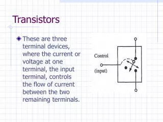
Download
1 / 18
190 likes | 224 Views
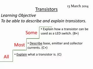
Learn about transistors as switches, biasing, biasing analysis, current gain, FETs, JFETs, CMOS, and operational amplifiers in this session. Understand how to use transistors effectively as switches and amplifiers for various applications.

E N D
Transistors as a switch Session 6b for Electronics and TelecommunicationsA Fairfield University E-CoursePowered by LearnLinc Electronics and Telecommunications
Module: Semiconductor Electronics(in two parts) • Text: “Electronics,” Harry Kybett, Wiley, 1986, ISBN 0-471-00916-4 • References: • Electronics Tutorial (Thanks to Alex Pounds) • Electronics Tutorial (Thanks to Mark Sokos) • 5 - Semiconductors, Diodes and Bipolar Transistors • 5 on-line sessions plus one lab • 6 - FETs, SCRs, Other Devices and Amplifiers • 5 on-line sessions plus one lab • Mastery Test part 3 follows this Module Electronics and Telecommunications
Section 6: FETs, SCRs, Other Devices and Operational Amplifiers • 0BJECTIVES:This section reviews additional important semiconductor devices and their applications. The Operational Amplifier is also studied. Electronics and Telecommunications
Section 6 Schedule: Electronics and Telecommunications
FET Summary • A voltage-controlled resistor • Channel material • N-channel FET • P-channel FET • FET types • Junction FET (JFET) • Metal Oxide Gate FET (MOSFET) • Complementary Symmetry MOSFET (CMOS) • Simple high input impedance amplifiers • Very effective as switches (Session 6b) Electronics and Telecommunications
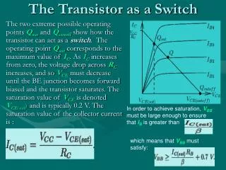
An NPN Switch • Open switch – no current • Closed switch – base current flows • For saturation (fully on)Ic ~ 0.1 amp • If = 100, Ib ~ 1 milliamp Electronics and Telecommunications
Better Biasing • Never leave transistor (or IC) inputs dangling • Noise sensitivity • Static discharge failures • Reduced leakage current sensitivity • Icb: reverse leakage current • R2conducts leakage current to ground Electronics and Telecommunications
Biasing Analysis • Desire 100 ma load current Electronics and Telecommunications
Biasing Analysis • Desire 100 ma load current • Base current >1 ma for saturation (=100) Electronics and Telecommunications
Biasing Analysis • Desire 100 ma load current • Base current >1 ma for saturation (=100) • Set I2 = 10 ma • Low impedance biasingfor reduced leakage sensitivity Electronics and Telecommunications
Biasing Analysis • Desire 100 ma load current • Base current >1 ma for saturation (=100) • Set I2 = 10 ma • R2 = 70 (68 )(Low impedance biasing;reduced leakage sensitivity) Electronics and Telecommunications
Biasing Analysis • Desire 100 ma load current • Base current >1 ma for saturation (=100) • Set I2 = 10 ma • R2 = 70 (68 )(Low impedance biasing;reduced leakage sensitivity) • R1 = 846 (820 ) • Note reduced current gainand higher power use Electronics and Telecommunications
More Current Gain • Cascade two transistors • Bias the first transistor for a smaller load current • The second transistor provides the higher current • Is the lamp on or off here? Electronics and Telecommunications
More Current Gain • Cascade two transistors • Bias the first transistor for a smaller load current • The second transistor provides the higher current • Is the lamp on or off here? • Q1 is on Electronics and Telecommunications
More Current Gain • Cascade two transistors • Bias the first transistor for a smaller load current • The second transistor provides the higher current • Is the lamp on or off here? • Q1 is on • Q2 is off Electronics and Telecommunications
An N-Channel JFET Switch • Vgg = 0; the JFET is on • Vgg = -5; the JFET is off Electronics and Telecommunications
A CMOS Inverter • Q1: N-channel MOSFET, Q2: P-channel MOSFET • If Vin is grounded • Q1 is off and Q2 is on • Vout is +5v • If Vin is +5 volts • Q2 is off and Q1 is on • Vout is 0 volts • Q1 and Q2 are FET switches(always opposite condition) Note: these MOSFETs are designed to be off for Vgs < 1 volt Electronics and Telecommunications
Section 6 Schedule: Electronics and Telecommunications