Download
1 / 18
190 likes | 215 Views
Explore UHF RFID system components and signal propagation for optimal performance and compliance with regulatory standards. Learn about antenna configurations, system losses, and factors affecting signal quality. Discover how to mitigate interference and enhance RFID reader performance in real-world applications.

E N D
UHF Gen2 RFIDPropagation View Prof. Roland Kueng
0 0 1 2 3 4 5 6 7 8 9 5 Starting Motivation Wanted: Smart Wireless Electronic Barcode which allows to create and operate an Internet-of-Things Needs: Ultra low cost Tags with a Global Standard behind to tag all goods and items Future: Upgrade Tag with Sensors
RFID Systems up to Edgeware RFID Reader System Decoupling Line to RFID - Application Enterprise Application Integration
Example: Dock Door Application Reader related risks • Mutual interference among readers • Co-channel interference • Adjacent channel interferences • Intersystem interferences
UHF Reader Block Diagram power amp TX antenna modulation switch RADIATING ANTENNA RX antenna signal processor synthesizer I Q D A direct conversionreceiver • Air Interface Options: • 2 Separated Antennas • 1 Antenna and Circulator • 1 Antenna and Directional Coupler
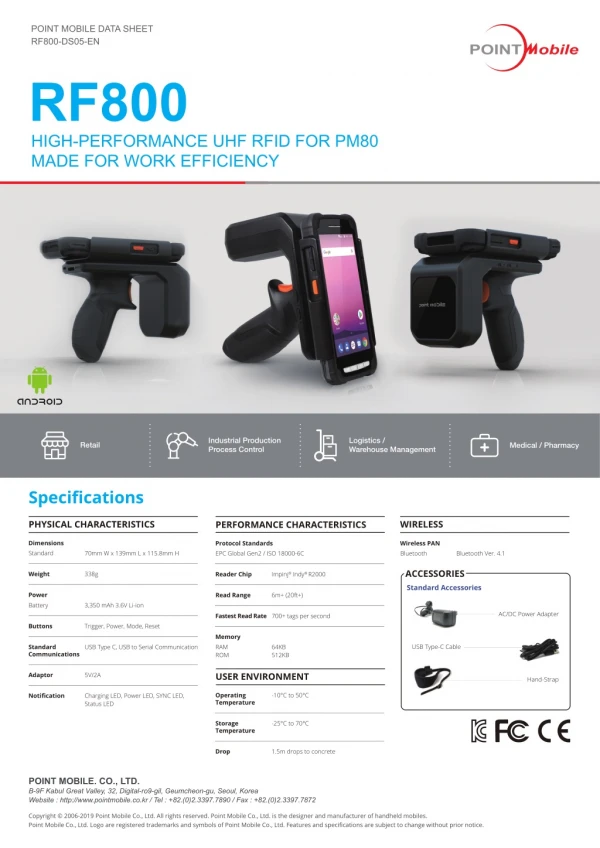
Details Reader Architecture Signal Processing - Sample Level on FPGA - Symbol Level on DSP - Air Protocol on DSP • RISC Processor • MAC • Reader Protocol • Interfaces • UHF Frontend • Direct Conversion Receiver • Carrier Suppression • Multi Antenna
FPGA ADC DAC DSP Synthesizer DC-RX Xscale TX Amp Supply Circulator Ethernet USB RS232 4 Antenna Ports Modern Reader Example
UHF Passive Tag Block Diagram RADIATING ANTENNA DC power control & signal sub carrier with processing data from reader unit memory backscatter modulator sub carrier with data from tag
Best what Radiation can do • The fundamental formula (d>> ) : • Pr = received power • Pt = transmitted power • Gt = transmit antenna gain • Gr = receive antenna gain • = wavelength • d = distance • n = propagation exponent • L = system loss factor • do = breakpoint distance for n>2 G = 4·Ae/2 Pt ·Gt = EIRP (limited by regulations*) 2/(4)2d2 Free space attenuation, n = 2 *Regulations: ETSI EN 320 208 US FCC Part 15
Path Loss 49 dB @ 8 m Path Loss 49 dB @ 8 m PassiveUHF RFID: Limited by Tag Power Consumption * EPC Class 1 Gen 2 -13…-17 dBm - 16 dBm received at tag * S/N= 35 dB + 33 dBm (2 W) - 71 dBm (0.1 nW) Gain = 7 dB • 22 dBm (6 μW)backscatter signal Receiver Noise: -99 dBm (F = 25 dB, B = 100 kHz) Reality: Additionally orientation losses, system losses, fading, n > 2 ... Additional noise sources, amplitude phase, TX to RX coupling
Fading - Problem for Passive Solutions Simple 2-Ray Model
UHF Signal Propagation Material Orientation • Test fixture with 73 Gen2 tags, equally spaced in air medium • Target read time: < 1 second
UHF Signal Propagation Multi-path reflections from metal (reinforcing in floors/ dock levellers and other objects), cause nulls and peaks that get worse with distance from the antenna.