Download
1 / 20
200 likes | 389 Views
Characterizing 11G Long Reach CEI Channels. John Mitchell Winchester Electronics. Agenda. Introduction to CEI Definition of a channel How to characterize channel performance Accounting for the driver, receiver and data An eye pattern based on statistics Conclusions.

E N D
Characterizing 11G Long Reach CEI Channels John Mitchell Winchester Electronics
Agenda • Introduction to CEI • Definition of a channel • How to characterize channel performance • Accounting for the driver, receiver and data • An eye pattern based on statistics • Conclusions Characterizing 11G Long Reach CEI Channels
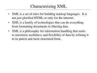
What is CEI? • Next Generation Common Electrical I/O Project • Will support various higher level interfaces including: • SFI (SERDES to Framer Interface) • SPI (System Packet Interface) • TFI (TDM-Fabric to Framer Interface) • Higher Density and/or lower cost interfaces for data rates up to 10+Gbps.
What is CEI? • Four versions are defined: • A 6G+ short reach link • 0 to 200mm link with up to one connector • Data lane(s) that support bit rates from 4.976 to 6+Gbps over Printed Circuit Boards. • A 6G+ long reach link • 0 to 1m link with up to two connectors • Data lane(s) that support bit rates from 4.976 to 6+Gbps over Printed Circuit Boards. • An 11G+ short reach link • 0 to 200mm link with up to one connector • Data lane(s) that support bit rates from 9.95 to 11+Gbps over Printed Circuit Boards. • An 11G+ long reach link • 0 to 1m link with up to two connectors • Data lane(s) that support bit rates from 9.95 to 11+Gbps over Printed Circuit Boards.
Typical Long Reach Application Backplane Total Transmission Line Length up to 1 meter. Transceiver Transceiver Plug-in Card A Plug-in Card B
Reference Model Driver Characteristics Channel Characteristics Receiver Characteristics
Long Reach Issues • Significant loss at high frequency • Significant loss dispersion over required bandwidth • Numerous transmission line transition points may cause reflections • Potential Skew Issues • Potential Crosstalk Issues • Various signal conditioning options
How to characterize the channel? Time Domain Frequency Domain • Pattern dependent • Eye may be closed • Can signal conditioning help? • How much loss is too much? • How does this relate to the time domain? • Can signal conditioning help?
Pulse Response Method H(ω) H(ω) Frequency Domain Interpolate Extrapolate DUT Channel Measurement S-Parameters Channel Response iFFT Characterize Total Channel Distortion Tx(t) H(t) Rx(t) Amplitude * = Time Domain Jitter Transmit Pulse Channel Response Pulse Response Thru Channel and Crosstalk Channels
Pulse Response Analysis • C0 cursor is placed at peak • Pre and Post cursors are placed at baud spaced intervals • Pre and Post cursors represent distortion • Relationship between C0 and the sum of all other cursors can be used to characterize the channel • The probability of cursors causing distortion can be determined based on the data pattern being transmitted on the channel C0 C+1 C+2 C+3 C+4 C-1
Drivers and Receivers are not Perfect Driver will jitter pulse in time Receiver may not sample at peak C0 C+1 C+2 C+3 C+4 C-1
Each Cursor has a Range of Values • Probability of driver and receiver behavior can be determined • This will set bounds on possible cursor positions for a given number of bits
Statistical Calculations on Measured Data Pulse Response These calculations can be automated and incorporated into test equipment or Matlab program Data Pattern Statistics + Driver Jitter Statistics + Receiver Sampling Statistics Statistical Data Eye + =
Statistical Data Eye • Each contour line represents the statistical eye opening for a given number of bits • The most red eye in this case represents BER of 1e-15 Courtesy of Anthony Sanders (Infineon Technologies)
Conclusion • OIF is developing a new method to characterize interconnect channels • Basis for characterization is measurement with VNA (complete and accurate) • The new method accounts for statistical variation in the data pattern and performance of driver and receiver • Results are in familiar Time Domain format and easy to interpret
Technology Demonstrations at Supercomm • Active test set-up in OIF Booth • Passive test set-up on Winchester Booth • Hall C3 - Booth #11831