Download
1 / 19
210 likes | 542 Views
Network Standards. OSI & TCP/IP. Figure 2-8: Hybrid TCP/IP-OSI Architecture. Figure 2-9: Physical and Data Link Layer Standards in a Single Network, Continued. Data Link Layer

E N D
Network Standards OSI & TCP/IP
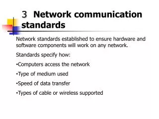
Figure 2-9: Physical and Data Link Layer Standards in a Single Network, Continued • Data Link Layer • Data link layer standards govern the transmission of frames across a single network—typically by sending them through several switches along the data link Frame Data Link A-B Host B Switch X1 Host A Switch X2
Figure 2-10: Internet and Data Link Layers in an Internet, Continued Frame X Packet In Network X: Two Destination Addresses: Packet: Host B (Destination Host) Frame: Router R1 Data Link A-R1 Switch Host A Switch Server Station Switch X1 Mobile Client Station Switch X2 Route A-B Router R1 Network X
Figure 2-10: Internet and Data Link Layers in an Internet, Continued To Network X Route A-B Router R1 Frame Y Data Link R1-R2 In Network Y: Two Destination Addresses: Packet: Host B (Destination Host) Frame: Router R2 Packet Router R2 Network Y To Network Z
Figure 2-10: Internet and Data Link Layers in an Internet, Continued Frame Z Packet Data Link R2-B Switch Z1 Host B Router R2 In Network Z: Two Destination Addresses: Packet: Host B (Destination Host) Frame: Host B Switch Z2 Mobile Client Stations Switch X2 Router Network Z
Figure 2-11: Internet and Transport Layer Standards, Continued 2. Transport Layer end-to-end (host-to-host) TCP is connection-oriented, reliable UDP is connectionless and unreliable Server Client PC 1. Internet Layer (usually IP) hop-by-hop (host-router or router-router) connectionless, unreliable Router 1 Router 2 Router 3
Ethernet Frame Preamble 10101010…. Start Delim. 10101011 Preamble (3 more octets) Destination Address (6 octets total) Destination Addr Source Address Source Address Length (2 octets) LLC header + data + (pad if < 46 octets) FCS (4 octets)
IP Datagram Packet 0 4 8 16 31 Vers Hlen TOS Length (in octets) Identifier Offset flags TTL Protocol Header Checksum Source IP Address Destination IP Address Options (0 – 44 octets) Data (Data + header <= 64 KB
Figure 2-18: Layered Communication on the Source Host The process begins when a browser creates an HTTP request message Application Process HTTP Message Passes Message Down to Transport Process Transport Process HTTP Message TCP Hdr Encapsulation of HTTP Message in Data Field of TCP Segment
Figure 2-18: Layered Communication on the Source Host, Continued • When a layer process (N) creates a message, it passes it down to the next-lower-layer process (N-1) immediately • The receiving process (N-1) will encapsulate the Layer N message, that is, place it in the data field of its own (N-1) message
Figure 2-18: Layered Communication on the Source Host, Continued Transport Process HTTP Message TCP Hdr Internet Process HTTP Message TCP Hdr IP Hdr Encapsulation of TCP Segment in Data Field of IP Packet
Figure 2-18: Layered Communication on the Source Host, Continued Internet Process HTTP Message TCP Hdr IP Hdr Data Link Process Eth Trlr HTTP Message TCP Hdr IP Hdr Eth Hdr Encapsulation of IP Packet in Data Field of Ethernet Frame
Figure 2-18: Layered Communication on the Source Host, Continued Data Link Process Eth Trlr HTTP Message TCP Hdr IP Hdr Eth Hdr Physical Process Physical Layer converts the bits of the frame into signals.
App Trans Int DL Phy Figure 2-20: Layered End-to-End Communication Routers Have Three Layers --- Each Router Port Has Two Layers (1&2) Switches Have Two Layers --- Each Switch Port Has One Layer (1) Source and Destination Hosts Have 5 Layers Source Host Switch 1 Switch 2 Router 1 Switch 3 Router 2 Destination Host
App Trans Int DL Phy Figure 2-21: Combining Horizontal and Vertical Communication Hypertext Transfer Protocol Transmission Control Protocol Internet Protocol Destination Host Source Host Switch 2 Router 1 Switch 3 Router 2 Switch 1
Figure 2-22: The Hybrid TCP/IP-OSI Architecture Broad Purpose Hybrid TCP/IP-OSI OSI TCP/IP Communication between applications Application (Layer 5) Application Application Presentation Session Internetworking Transport (Layer 4) Transport Transport Internet (Layer 3) Network Internet Transmission within a single LAN or WAN Data Link (Layer 2) Data Link Use OSI Standards Here Physical (Layer 1) Physical
Figure 2-26: Characteristics of Protocols Discussed in the Chapter Layer Protocol Connection- Oriented /Connectionless Reliable/ Unreliable 5 (App) HTTP Connectionless Unreliable 4 (Transport) TCP Connection- oriented Reliable 4 (Transport) UDP Connectionless Unreliable 3 (Internet) IP Connectionless Unreliable 2 (Data Link) Ethernet Connectionless Unreliable Note: Only TCP is connection-oriented and reliable