Download
1 / 26
290 likes | 390 Views
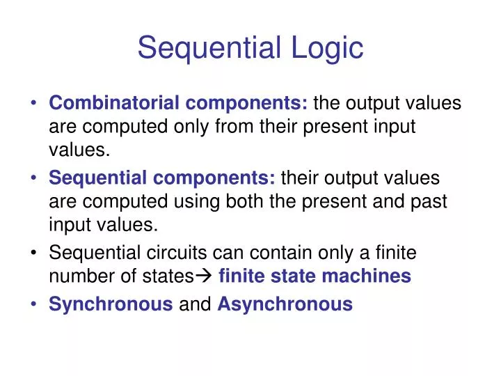
Sequential Logic. Combinatorial components: the output values are computed only from their present input values. Sequential components: their output values are computed using both the present and past input values.

E N D
Sequential Logic • Combinatorial components: the output values are computed only from their present input values. • Sequential components: their output values are computed using both the present and past input values. • Sequential circuits can contain only a finite number of states finite state machines • Synchronous and Asynchronous
Sequential Circuits • Contains Memory Elements • Asynchronous sequential circuits change their state and output values when input changes • Synchronous sequential circuits change their output values at fixed points of time, which are specified by the rising or falling edge of a clock signal • Clock period is the time between successive transitions in the same direction • Active high – state changes occur at the clock’s rising edge( on higher voltage) • Active low – state changes occur at the clock’s falling edge( on lower voltage)
4 Basic types of Flip-Flops • SR, JK, D, and T • JK ff has 2 inputs, J and K need to be asserted at the same time to change the state • D ff has 1 input D (DATA), which sets the ff when D = 1 and resets it when D = 0 • T ff has1 input T (Toggle), which forces the ff to change states when T = 1 • SR ff has 2 inputs, S (set) and R (reset) that set or reset the output Q when asserted
Gated D-Latch • Ensures S and R inputs never equal to 1 at the same time • Useful in control application where setting or resetting a flag to some condition is needed • Stores bits of information • Constructed from a gated SR latch and a Data latch
D Flip-Flop Q+ = Next State Characteristics : Synchronous Avoids the instability of RS flip-flop Retains its last input value To set the ff, place 1 on D input and pause the CK input To reset, place 1 on D input and pause the CK input
JK – Flip Flop J – Set K – Reset J = K = 0 – output does not change J = K = 1 – invert the outputs
T Flip-Flop T = 1 force the state change T = 0 state remain the same
How to use JK to implement D Flip-Flop D ff’s property: When in = 0, the out(Q+) = 0. When in = 1, the out(Q+) is 1 invert K invert K D
How to use JK to implement T Flip-Flop T ff’s property: When in = 0, the out(Q+) = no change When in = 1, the out(Q+) is = complement No change State change T
How to use D to implement JK Flip-Flop (Q ) = no state change (Q’) = state change D = JQ’ + K’Q
How to use D to implement JK Flip-Flop D = JQ’ + K’Q J K
How to use T to implement JK Flip-Flop T = KQ + JQ’
How to use T to implement JK Flip-Flop T = KQ + JQ’
How to use D to implement T Flip-Flop D = TQ’ + T’Q
How to use D to implement T Flip-Flop D = TQ’ + T’Q T
How to use T to implement D Flip-Flop T = DQ’ + D’Q
How to use T to implement D Flip-Flop T = DQ’ + D’Q D
SR-Flip Flop SET RESET SET RESET
SR-Flip Flop • Asynchronous • If S=0 and R=1, Q is set to 1, and Q’ is reset to 0 • IF R=0 and S=1, Q is reset to 0, and Q’ is set to 1 • If S=1 and R=1, Q and Q’ maintain their previous state • If S=0 and R=0, a transition to S=1, R=1 will cause oscillation
Clocked SR Flip-Flop Similar to SR Flip-flop but with extra control input C, which enables or disables the operation of S and R inputs. C=1 Enabled C=0 Disabled, circuit persists in preceding state
Instability • RS flip-flops can become unstable if both R and S are set to 0 • All sequential elements are fundamentally unstable under certain conditions • Invalid transitions • Transitions too close together • Transitions at the wrong time
Edge and level-triggered Flip Flop • Digital circuit often form loops, flip-flops oscillations can • Oscillation will not occur because by the time an output change cause an input change, the activating edge of the CK signal will be gone • Positive edge triggered – ff responds to a positive going edge of clock • Negative edge triggered – responds to a negative-going edge
Positive-edge-triggered D Flip-Flop When CLK=0 the master latch is open and the content of D is transferred to QM When CLK=1 the master is closed and its output is transferred to the slave Master and slave latches are never enabled at the same time
References • www.play-hookey.com/digital • www.infopad.eecs.berkeley.edu/~icdesign/SLIDES/slides6.pdf • www.cs.mun.ca/~paul/cs3724/material/web/notes/node14.html • Dos Reis, Assembly Language and Computer Architecture Using C++ and Java