Download
1 / 22
350 likes | 660 Views
A lodestar on pad groove pattern design with slurry flow analysis and visualization experiments in CMP process. 2006 ICPT. Keiichi Kimura, Katsuya Nagayama, Yosuke Inatsu, Panart Khajornrungruan Department of Mechanical Information Science and Technlogy, Kyushu Institute of Technology

E N D
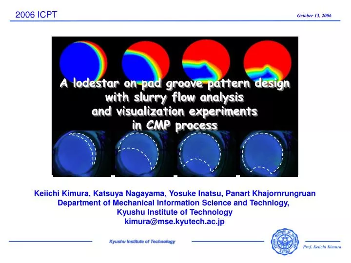
A lodestar on pad groove pattern design with slurry flow analysis and visualization experiments in CMP process 2006 ICPT Keiichi Kimura, Katsuya Nagayama, Yosuke Inatsu, Panart Khajornrungruan Department of Mechanical Information Science and Technlogy, Kyushu Institute of Technology kimura@mse.kyutech.ac.jp
Outline • Introduction • Computational analysis method • Visualization experiment method • Basic slurry flow • Slurry flow simulation and visualization experiments • Lodestar of groove pattern design • Conclusion
next Configuration of CMP machine & process Material removal = Interaction among 3 factors Silicon Wafer wafer surface Slurry Polishing Pad slurry polishing pad
Silicon wafer V Polishing pad next Material removal between wafer and pad surface wafer and pad contact physical & chemical contact polishing conditions polishing speed polishing pressure wafer surface material & asperity slurry flow supply & drainage slurry chemical & particles polishing pad material, surface asperity
W2 q f 200 wafer 122.5 f 455 W1 polishing pad next Configuration of CMP model & polishing pad pitch of grooves : 2 mm width of groove : 1 mm width of land : 1 mm depth of groove : 1 mm (a) Concentric groove pattern a angle bet. grooves: 11.25 deg. (32 divisions) width of groove : 1 mm depth of groove: 1 mm (b) Radial groove pattern
next Computational model between wafer and groove pad Heat fluid analysis code : FLUENT 6.2 Pad Edge - Continuity equation Wafer - Navier-Stokes equation Grooves Pad center - Diffusion equation for slurry transportation Groove Gap Height wafer wafer - Concentric groove Lattices : 1,000,000 - Radial groove Lattices : 600,000 m m 10 10 m m gap gap 1 mm 1 mm pad pad groove groove 1 mm 1 mm Groove cross Groove cross - - section section (not in scale) (not in scale)
video camera UV light source fluorescent light DI water + fluorescent agent quartz glass polishing pad next Experimental set-up for slurry flow visualization - Quartz glass : f 200 (Supersil-P30 / ShinEtsu Quartz) - Fluid (Slurry) : DI water - Fluorescent agent : FWP-1 / Karl Deutsch - Ultraviolet light source : High pressure Mercury lamp (SHG-200/Mejiro Precision) - Polishing machine : NANOTECH 450-FODCAb/Nanotech Machines)
next Basic slurry flow between wafer and pad Opposite direction area : jammed flow Equal direction area : smooth flow 1. Slurry flows in thin space between wafer and polishing pad 2. Slurry flow is affected by the motion of wafer and polishing pad
next Slurry movement on polishing pad Grooves on polishing pad 1. Slurry transportation canal 2. Slurry reservoir slurry supply : (a) Groove pattern on pad surface (b) Groove cross section geometry : (c) Pad surface asperity polishing : (a) Groove pattern on pad surface slurry drainage (b) Groove cross section geometry
next Slurry flow simulation : No-groove pad [A] W1 W2 [B] 1 slurry flows in from right side 2 slurry spreads in area of [A] 3 slurry flows down in left area 4 slurry delays flowing in area [B] - No-groove pad - W1 : 60 min-1, W2 : 60 min-1 - slurry flow at 5mm below wafer
next Slurry flow simulation : Concentric groove pad simulation • Slurry flow in from right side of wafer • Slurry spreads around from upper side of wafer followed by rotation of wafer • Slurry flow delays at bottom side of wafer due to opposite rotation of wafer and pad • Shape of delayed slurry flow area is slightly different from no-groove pad • Concentric groove pattern can take in and reserve slurry beneath wafer Slurry flow at 5 mm below wafer : W1=60 min-1 : W2=60 min-1 Polishing pad rotation Wafer rotation
next Slurry flow simulation : Concentric groove pad simulation W1 > W2 • Slurry flows is slightly different from the case of W1=W2. • 2. Slurry flowing time over whole wafer is short. • 3. Delayed slurry flow area is small. • 4. Pad rotation influences slurry flow strongly. Slurry flow at 5 mm below wafer : W1=90 min-1 : W2=30 min-1 Polishing pad rotation Wafer rotation
next Slurry flow simulation : Concentric groove pad simulation W1 < W2 • Slurry flows same as the • case of W1=W2. • 2. Slurry flowing time over whole wafer is not short. • 3. Delayed slurry flow area is large. • 4. Influencesof wafer rotation for slurry flow is not much. Slurry flow at 5 mm below wafer : W1=30 min-1 : W2=90 min-1 Polishing pad rotation Wafer rotation
next Slurry flow simulation : Concentric groove pad simulation • Slurry flow in from right side of wafer • Slurry spreads around from upper side of wafer followed by rotation of wafer • Slurry flow delays at bottom side of wafer due to opposite rotation of wafer and pad • Shape of delayed slurry flow area is slightly different from no-groove pad • Concentric groove pattern can take in and reserve slurry beneath wafer Slurry flow at 5 mm below wafer : W1=60 min-1 : W2=60 min-1 Polishing pad rotation Wafer rotation
next Slurry flow experiment : Concentric groove pad visualization experiment 1. Concentric groove pattern can take in and reserve slurry beneath wafer 2. Delayed slurry flow area is existed at the bottom side of wafer : W1=30 min-1 : W2=30 min-1 Polishing pad rotation Wafer rotation
next Slurry flow analysis : Radial groove pad simulation 1. Radial groove pattern can take in slurry, and spread as sweeping fan shape 2. Slurry drainage is carried out quickly 3. Radial groove gives great influences for slurry flow. Slurry flow at 5 mm below wafer : W1=60 min-1 : W2=60 min-1 Polishing pad rotation Wafer rotation
next Slurry flow experiment : Radial groove pad2 visualization experiment 1. Radial groove pattern can take in slurry, and spread as sweeping fan shape 2. Slurry drainage is carried out quickly 3. Radial groove gives great influences for slurry flow. : W1=30 min-1 : W2=30 min-1 Polishing pad rotation Wafer rotation
next Geometry of combined groove Concentric groove Radial groove Combined groove + = Concentric groove pad : good to take in and reserve slurry + Radial groove pad : good to drain slurry quickly
next Slurry flow simulation : Combined groove pad simulation • Slurry flow on combined groove pad is similar to that of concentric groove pad 2. Delayed slurry flow area is disappeared 3. Slurry replacement over whole wafer is completed quickly Slurry flow at 5 mm below wafer : W1=60 min-1 : W2=60 min-1 Polishing pad rotation Wafer rotation
next Lodestar of groove pattern design • Basic functions of grooves on polishing pad are … • (a) to transport slurry beneath wafer • (b) to reserve slurry • (c) to drain slurry to outside of polishing pad 2. Concentric grooves have functions of (a) and (b). - grooves are closed shape in rotating direction and no open orifice 3. Radial grooves have function (c). - all grooves have open orifice 4. Combined grooves have functions (a), (b) and (c). - it is important to combine concentric grooves and radial grooves
next Conclusion • Computational analysis and visualization experiments • were attempted on slurry flow in CMP polishing pad. 2. Computational analysis and visualization experiments provided similar phenomena each other. 3. Basic function of groove pattern such as concentric groove and radial groove is analyzed with analysis and experiments. 4. Advantages on combined grove is analyzed. 5. Lodestar for groove pattern design is established.
next Acknowledgment We are indebted to Dr. K. Hieda, Dr. K. Kuriyama and JSR corporation for their great support and discussion with us on the research. We express plenty of appreciation to them.