Download

1 / 14
140 likes | 168 Views
Learn about assembly constraints in CAD designs, such as Mate, Flush, Angle, Insert, and more. Discover how to define relationships between components, remove degrees of freedom, and utilize base components. Edit, pattern, replace, and work with subassemblies effectively.

E N D
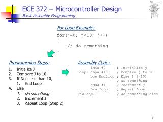
Assembly Constraints • Assembly constraints are parameters that define geometric relationships between components in a CAD assembly • Constraints include Mate/Flush Angle Tangent Insert
Degrees of Freedom • A component floating in space has six degrees of freedom • Degrees of freedom are systematically removed in an assembly until only the desired components are allowed to move 3 rotations around X, Y, and Z axes 3 translations along X, Y, and Z axes
Mate Constraint • Constrains two faces, edges, points, or axes together • Red arrows represent normal vectors and point toward each other
Flush Constraint • Constrains two faces or work features together • Normal vectors will point in the same direction
Angle Constraint • Constrains two faces or edges at an angle to one another • Normal vectors parallel to each other equal 0° angle
Insert Constraint • Constrains a cylinder flush into a hole
Tangent Constraint • Constrains a curved surface to a plane or another curved surface
Base Component • First component placed in an assembly should be a fundamental part or subassembly • E.g., a frame or base plate, on which the remainder of the assembly is attached • First component in an assembly file sets orientation of subsequent parts and subassemblies
Grounded Component • When the first component is placed in the assembly, its origin is coincident and aligned with the assembly coordinate origin • All degrees of freedom are removed from the first component • Base component will be grounded and should be left that way
Patterning Component • Function duplicates one or more components • Arranges the resulting occurrences in a circular or rectangular pattern
Replace Component • Design process is often non linear, so one or more components in an assembly may need replacement • New component placed in the same location as the original component, but assembly constraints may be deleted
Editing Components • Double click on a component to exit the assembly environment and enter part environment • Other components in the assembly will become translucent • When finished editing a part, exit the part environment and return to the assembly environment
Subassemblies • Group of components constrained to act as one component in a larger assembly