Download
1 / 4
50 likes | 73 Views
Protection scheme required for the protection of power system components against abnormal conditions such as faults etc., and that essentially consists of protective relaying and circuit breaker. Protective relay senses the fault and determines the location of fault. Then, protective relay sends the tripping command to the circuit breaker. Therefore, proper care should be taken in designing and selecting an appropriate relay which is reliable, efficient and fast in operation. The voltage transformer and current transformer continuously measure the voltage and current of an electrical system and are responsible to give feedback signals to the relays to enable then to detect abnormal conditions. This paper describes differential protection for power transformer, especially the rating of purposed system is 100 MVA, 230 kV 33 kV at substation. Thida Win | Hnin Nandar Maung | Ye Min Hein "Differential Protection of Power Transformer in Substation" Published in International Journal of Trend in Scientific Research and Development (ijtsrd), ISSN: 2456-6470, Volume-3 | Issue-5 , August 2019, URL: https://www.ijtsrd.com/papers/ijtsrd27995.pdf Paper URL: https://www.ijtsrd.com/engineering/electrical-engineering/27995/differential-protection-of-power-transformer-in-substation/thida-win<br>

E N D
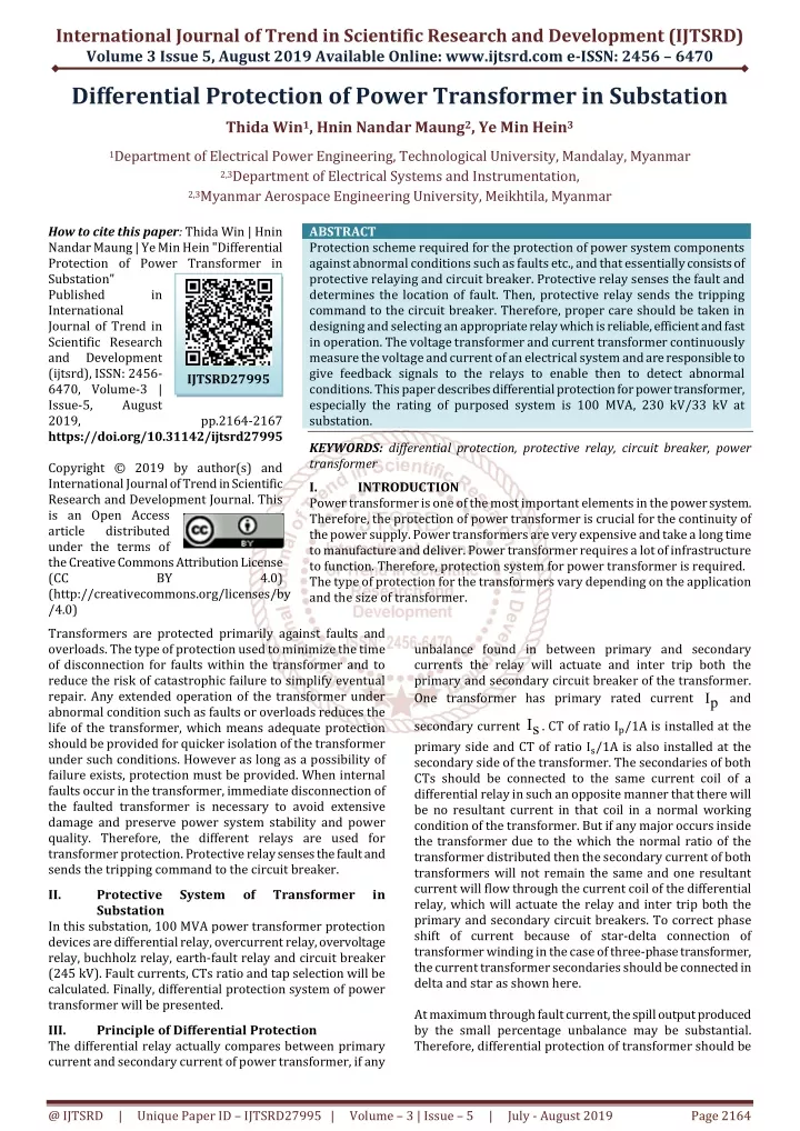
International Journal of Trend in Scientific Research and Development (IJTSRD) Volume 3 Issue 5, August 2019 Available Online: www.ijtsrd.com e-ISSN: 2456 – 6470 Differential Protection of Power Transformer in Substation Thida Win1, Hnin Nandar Maung2, Ye Min Hein3 1Department of Electrical Power Engineering, Technological University, Mandalay, Myanmar 2,3Department of Electrical Systems and Instrumentation, 2,3Myanmar Aerospace Engineering University, Meikhtila, Myanmar How to cite this paper: Thida Win | Hnin Nandar Maung | Ye Min Hein "Differential Protection of Power Transformer in Substation" Published in International Journal of Trend in Scientific Research and Development (ijtsrd), ISSN: 2456- 6470, Volume-3 | Issue-5, August 2019, https://doi.org/10.31142/ijtsrd27995 Copyright © 2019 by author(s) and International Journal of Trend in Scientific Research and Development Journal. This is an Open Access article distributed under the terms of the Creative Commons Attribution License (CC BY (http://creativecommons.org/licenses/by /4.0) Transformers are protected primarily against faults and overloads. The type of protection used to minimize the time of disconnection for faults within the transformer and to reduce the risk of catastrophic failure to simplify eventual repair. Any extended operation of the transformer under abnormal condition such as faults or overloads reduces the life of the transformer, which means adequate protection should be provided for quicker isolation of the transformer under such conditions. However as long as a possibility of failure exists, protection must be provided. When internal faults occur in the transformer, immediate disconnection of the faulted transformer is necessary to avoid extensive damage and preserve power system stability and power quality. Therefore, the different relays are used for transformer protection. Protective relay senses the fault and sends the tripping command to the circuit breaker. II. Protective System Substation In this substation, 100 MVA power transformer protection devices are differential relay, overcurrent relay, overvoltage relay, buchholz relay, earth-fault relay and circuit breaker (245 kV). Fault currents, CTs ratio and tap selection will be calculated. Finally, differential protection system of power transformer will be presented. III. Principle of Differential Protection The differential relay actually compares between primary current and secondary current of power transformer, if any ABSTRACT Protection scheme required for the protection of power system components against abnormal conditions such as faults etc., and that essentially consists of protective relaying and circuit breaker. Protective relay senses the fault and determines the location of fault. Then, protective relay sends the tripping command to the circuit breaker. Therefore, proper care should be taken in designing and selecting an appropriate relay which is reliable, efficient and fast in operation. The voltage transformer and current transformer continuously measure the voltage and current of an electrical system and are responsible to give feedback signals to the relays to enable then to detect abnormal conditions. This paper describes differential protection for power transformer, especially the rating of purposed system is 100 MVA, 230 kV/33 kV at substation. KEYWORDS: differential protection, protective relay, circuit breaker, power transformer I. INTRODUCTION Power transformer is one of the most important elements in the power system. Therefore, the protection of power transformer is crucial for the continuity of the power supply. Power transformers are very expensive and take a long time to manufacture and deliver. Power transformer requires a lot of infrastructure to function. Therefore, protection system for power transformer is required. The type of protection for the transformers vary depending on the application and the size of transformer. IJTSRD27995 pp.2164-2167 4.0) unbalance found in between primary and secondary currents the relay will actuate and inter trip both the primary and secondary circuit breaker of the transformer. One transformer has primary rated current I and p secondary current sI . CT of ratio I?/1A is installed at the primary side and CT of ratio I?/1A is also installed at the secondary side of the transformer. The secondaries of both CTs should be connected to the same current coil of a differential relay in such an opposite manner that there will be no resultant current in that coil in a normal working condition of the transformer. But if any major occurs inside the transformer due to the which the normal ratio of the transformer distributed then the secondary current of both transformers will not remain the same and one resultant current will flow through the current coil of the differential relay, which will actuate the relay and inter trip both the primary and secondary circuit breakers. To correct phase shift of current because of star-delta connection of transformer winding in the case of three-phase transformer, the current transformer secondaries should be connected in delta and star as shown here. At maximum through fault current, the spill output produced by the small percentage unbalance may be substantial. Therefore, differential protection of transformer should be of Transformer in @ IJTSRD | Unique Paper ID – IJTSRD27995 | Volume – 3 | Issue – 5 | July - August 2019 Page 2164
International Journal of Trend in Scientific Research and Development (IJTSRD) @ www.ijtsrd.com eISSN: 2456-6470 provided with a proportional bias of an amount which exceeds in effect the maximum ratio deviation.[3] IV. Types of Differential Relay The differential protection relay is mainly classified into three categories. These are: 1.Current differential relay 2.Biased or percentage differential relay 3.Voltage balance differential relay A.Current Differential Relay A relay which senses and operates the phase difference between the current entering into the electrical system and the current leaving the electrical system is called a current differential relay. An arrangement of overcurrent relay connected to operate as a differential relay is shown in the Figure 1. The dotted line shows the section which is used to be protected. The current transformer is placed at both the ends of the protection zone. The secondary of the transformers is connected in series with the help of the pilot wire. Thereby, the current induces in the CTs flows in the same direction. The operating coil of the relay is connected on the secondary of the CTs. In the normal operating condition, the magnitude of current in the secondary of the CTs remains same. The zero current flows through the operating coil. On the occurrence of the fault, the magnitude of the current on the secondary of CTs becomes unequal because of which the relay starts operating. Figure2. Biased or Percentage Differential Relay C.Voltage Balance Differential Relay The current differential relay is not suitable for the protection of the feeders. For the protections of the feeders, the voltage balance differential relays are used. In this arrangement, the two similar current transformers are connected at either end of the system element under protection using pilot wires.[1][2] Figure3. Voltage Balance Differential Relay V. Differential protection is normally applied to transformers 10 MVA and above or depending upon its criticality. The following factors affect the differential current in transformers and are considered while applying differential protection. These factors can result in a differential current even under balanced power in and out conditions. Differential protection is, as the name implies, a form of protection that utilizes measurements to detect differences. This is done by bounding an area by two measurements and evaluating the difference between the measurements. The basic principle applies as the sum of all currents flowing into the system must equal zero according to Kirchhoff’s current law. The difference is that in high voltage power transformer applications, the magnetizing current becomes too large to be neglected. Besides the magnetizing current, several sources of bias exist. One such source is the CTs used for measuring the currents. These are utilized due to the practicalities of measuring currents in a high power system. The bias from the CTs is proportional to the through current while the CTs are operating in the linear range. The error depends on the type of CT. The transformer differential protection setting can be calculated by the following equations.[4][5] Mathematical Formulations Figure1. Current Differential Relay B.Biased or Percentage Differential Relay This is the most used form of differential relay. Their arrangement is same as that of the current differential relay; the only difference is that this system consist an additional restraining coil connected in the pilot wires as shown in Figure 2 and current flows in both CTs flows through it. E p r.m.s short-circuit current, sI = (1) X p @ IJTSRD | Unique Paper ID – IJTSRD27995 | Volume – 3 | Issue – 5 | July - August 2019 Page 2165
International Journal of Trend in Scientific Research and Development (IJTSRD) @ www.ijtsrd.com eISSN: 2456-6470 100 S I = I (min -1) (11) diff min short circuit MVA (2) X % Differential current at maximum tap, max diff MVA sc fI Fault Current, (3) (1-max I I ) (12) 3 kV I I av max MVA 3 nI = Transformer full load current, rated kV (4) Tap changer error (13) I I av MVA p Current setting at primary (5) primary at ratio CT I (14) base primary 3 kV I primary p Current setting at secondary (6) secondary at ratio CT 2 MVA I (15) secondary base average V 3 kV (7) sec CT ondary ratio 1 V ) position tap : max V ( primary position tap : min Matching actor for primary (16) I Current at base primary V , maximum position tap MVA Matching factor for secondary (17) CT ratio secondary (8) I I max base secondary 3 V max tap position VI. Calculation Result Data of Differential Current Setting The Kirchoff’s Current Law is the main concept of this protection, when one node the summation of currents flowing in and out will be zero. The current setting can be calculated by using the following conditions. 1.Minimum present load condition 2.Maximum present load condition 3.Rated current carrying capacity of ACSR 795 MCM 4.Primary rated current condition 5.Fault condition 6.Rated capacity of twin bundle ACSR 795 MCM Current at V , minimum position tap MVA (9) I min 3 V min tap position V , Current at average position tap MVA I (10) av 3 V average tap position Differential current at minimum tap, The calculation result data of differential current setting is shown in Table 1. Table1. Result Data of Differential Current Setting Condition Base Current (A) Matching Factor Differential Current Setting (pu) Primary Secondary Primary Secondary Primary Secondary 1 251.02 1749.55 0.1992 0.2286 0.37 0.37 2 251.02 1749.55 0.1992 0.2286 0.57 0.57 3 251.02 1749.55 0.1992 0.2286 0.89 0.89 4 251.02 1749.55 0.1992 0.2286 3.58 3.58 5 251.02 1749.55 0.1992 0.2286 5.7 5.7 6 251.02 1749.55 0.1992 0.2286 6.2 6.2 The calculation results are between 0.37 pu and 6.2pu. In existing data from the substation, 0.2 pu is set up minimum current setting and 7 pu is set up maximum current setting. Table2. Comparison of Calculation Result and Data Used in the Substation Result Data of Calculation Rated Current (A) 251.02 250-500/5 Feeder Data from Substation Rated Current (A) 251.02 Differential Current Setting 0.2 - 7 Differential Current Setting 0.37-6.2 CT ratios CT ratios X’mer primary side 250-500/5 X’mer secondary side 1749.5 1000-2000/5 0.2 - 7 1749.55 1000-2000/5 0.37-6.2 @ IJTSRD | Unique Paper ID – IJTSRD27995 | Volume – 3 | Issue – 5 | July - August 2019 Page 2166
International Journal of Trend in Scientific Research and Development (IJTSRD) @ www.ijtsrd.com eISSN: 2456-6470 Feeder 1 300.05 200-400/5 - 300.5 200-400/5 - Feeder 2 227.09 200-400/5 - 227.09 200-400/5 - Feeder 3 343.79 200-400/5 - 343.79 200-400/5 - Feeder 4 296.19 200-400/5 - 296.19 200-400/5 - VII. Nowadays, electrical energy demand is increasing and power shortages are more increased because of various faults. In order to minimize these problems, the better power system protection schemes are needed. The less time of sensing faults and clearing faults can build the more power system stability. The assessing of time dial setting is very important because the operating time of the relay is directly proportional to the time dial setting. The circuit breaker can clear the fault quickly if the relay sends the fault information with the fastest speed to breaker. It can cause less damage to electrical equipments. Conclusion VIII. [1]QaziArsalan Hamid, “Differential Protection Scheme basic and 5 MVA Transformer Protection Calculation”, 2018. References [2]Robert Morkel, “Differential Relay”, 2017. [3]J. Lewis Blackburn and Thomas J. Domin, “Protection Relaying Principle and Application”, Third edition, 2016. [4]L. G. Hewitson, Mark Brown and Ramesh Balakrishnan, “Pratical Power System Protection”, 2004. [5]Noelle D. Humenick, “IEEE Guide for Protection Relay Application to Power Transformer”, 2000. @ IJTSRD | Unique Paper ID – IJTSRD27995 | Volume – 3 | Issue – 5 | July - August 2019 Page 2167