Download
1 / 23
230 likes | 269 Views
This paper discusses a compact RF module for ATE emphasizing high throughput RF function testing with full 4-channel resources integration. It compares new RF-SiP and board construction technologies to conventional methods, highlighting key performance metrics like dynamic range and settling time.

E N D
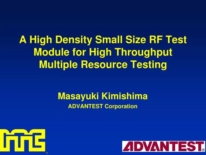
A High Density Small Size RF Test Module for High ThroughputMultiple Resource Testing Masayuki Kimishima ADVANTEST Corporation
Purpose • Trend of RF Test • Increasing Test Ports of Devices • Requirement for Low Test Cost • Requirements for RF ATE • A Number of Simultaneous Measurement • Higher Throughput of RF Function Test • -Our Target of RF Module for ATE- • Full 4-cHResources Integration with Compact Size • High Throughput of RF Function Test
Outline • Comparison of New and Conventional RF Module • RF-SiP and RF board Construction • Core Technologies of RF-SiP - VNA Front-End SiP - High Speed SW Technology - RF Synthesizer SiP • Performance of New RF Module • Conclusion
Conventional RF Module ConstructionBased on “RF-HBIC and Coaxial Cable” • Circuit Construction • RF-HBIC • RF Interconnection • Coaxial Cable • Frequency Synthesizer • YIG-Tuned Oscillator • Signal SW and Attenuator Circuits • PIN Diode, or Conventional HEMT • Facing Difficulties in realization of • Multiple Resource Integration • Higher Throughput
New RF Module ConstructionBased on “RF-SiP and RF board” • Circuit Construction • RF-SiP • RF Interconnection • BGA & RF board • Frequency Synthesizer • SiP Integration by PLL-LSI • Signal SW and Attenuator Circuits • High Speed SW and ATT MMICs • Achievement of Compact RF Module with • Full 4-cH Multiple Resources • Higher Throughput per cH
Structure of New RF Module Each Boards for 4-cH Volume Corresponds to“ 1/15 ” with Conventional Structure
Can Operate Each of 4-cH Individually Resource Construction of RF Module New RF Module Conventional RF Module
Outline • Comparison of New and Conventional RF Module • RF-SiP and RF board Construction • Core Technologies of RF-SiP - VNA Front-End SiP - High Speed SW Technology - RF Synthesizer SiP • Performance of New RF Module • Conclusion
Structure of RF-SiP ALL SiPs are the same size of 20mm sq.
RF Front-End Diagram for One Channel RF Front-End Board RF Synthesizer Board
Outline • Comparison of New and Conventional RF Module • RF-SiP and RF board Construction • Core Technologies of RF-SiP - VNA Front-End SiP - High Speed SW Technology - RF Synthesizer SiP • Performance of New RF Module • Conclusion
Measured Data of VNA-FE SiP Accuracy Conversion Gain and Noise Figure Dynamic range@1MHz BW, Freq-input : 2GHz = Pin_max - (Floor Noise + NF + Gain) - BW = + 10 - (-174 + 38 - 10) - 60 = 96 dB
Outline • Comparison of New and Conventional RF Module • RF-SiP and RF board Construction • Core Technologies of RF-SiP - VNA Front-End SiP - High Speed SW Technology - RF Synthesizer SiP • Performance of New RF Module • Conclusion
Settling Time of HEMT Device Definition of Settling Time Our Definition is 0 to 99.9% (0.01dB) Comparison of Settling Time for HEMTs
This Work Conventional HEMT Measurement Great Improvement on Settling Time Simulation Measured Data of SP4T Switch MMIC Frequency Characteristics Settling Time
Outline • Comparison of New and Conventional RF Module • RF-SiP and RF board Construction • Core Technologies of RF-SiP - VNA Front-End SiP - High Speed SW Technology - RF Synthesizer SiP • Performance of New RF Module • Conclusion
Block Diagram of RF Synthesizer SiP(Fractional-N Frequency Synthesizer) 13 VCOs PLL-LSI
Measured Data of Multi-Band VCOs(Frequency Response & Phase Noise) @ 1MHz off carrier
Fraction Integer 48-bit, 4th-Order MASH Architecture - Step Size < 100 uHz - Quantization Noise Shaping Around 400kHz Loop BW Integer Fraction Block Diagram of Fractional-N Frequency Divider
Outline • Comparison of New and Conventional RF Module • RF-SiP and RF board Construction • Core Technologies of RF-SiP - VNA Front-End SiP - High Speed SW Technology - RF Synthesizer SiP • Performance of New RF Module • Conclusion
Performance of New RF Module Dynamic Range of VSG Frequency Settling Time of VSG < 150 usec Conventional : 800 usec
Conclusion Compact Size RF Test Module with • Full 4-cH Resource Integration • Using RF-SiP and RF board Instead of Hybrid-IC and Coaxial Cable • Elimination of YIG Oscillator and PIN-Diode Switch • High Throughput of RF Function Test • High Speed Switch/Attenuator MMIC • VCO Base RF Synthesizer