Download
1 / 22
220 likes | 381 Views
ARM Microprocessor. “MIPS for the Masses”. Brief History. ARM (Advanced Risc Machine) Microprocessor was based on the Berkeley/Stanford Risc concept Originally called Acorn Risc Machine because developed by Acorn Computer in 1985

E N D
ARM Microprocessor “MIPS for the Masses”
Brief History • ARM (Advanced Risc Machine) Microprocessor was based on the Berkeley/Stanford Risc concept • Originally called Acorn Risc Machine because developed by Acorn Computer in 1985 • Financial troubles initially plagued the Acorn company but the ARM was rejuvenated by Apple, VLSI technology, and Nippon Investment and Finance
Basics • Only 25 basic instruction types • 3 stage instruction pipeline • All instructions are one word long • All instructions are predicated
Basics (Contd.) • All data processing instructions operate on registers only • All data processing instructions can use the barrel shifter (an interesting and unique feature) to shift or rotate an operand • Can operate in either big or little endian mode
Pipeline • 3 stage: fetch; decode; execute
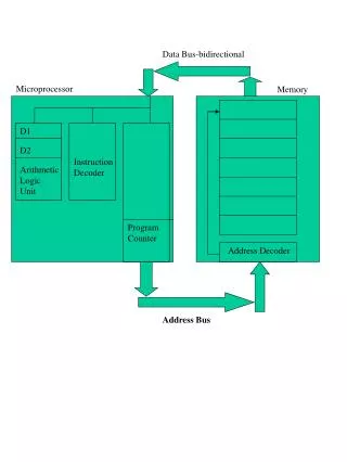
Memory • Arm is a 32 bit microprocessor with one word being 32 bits long • Memory is byte-oriented; each byte of memory has its own unique address • Must use an address divisible by 4 to access a word though
Memory (contd.) • ARM has a 26 bit wide addressing range which allows 64 mb of memory to be directly addressed • Memory Access: Register Indirect Addressing Pre and Post Indexed Addressing PC Relative Addressing Byte and Word Addressing
Registers • 32 bit registers: 13 general purpose registers, R0 to R12 R13 generally used as a Stack register R14 as the Link register R15 is the Program Counter and Status register
Program Counter (PC) • Program Counter is in bits 2 – 25 of R15 • After fetching an instruction, PC is incremented to next word • PC only needs to be 24 bits in length, though it can address a 26 bit address space – instructions must start at a word boundary thus 2 least significant bits must be zero
Status Register • Status register bits indicate either processor mode, fast interrupt mode, normal interrupt mode, and also the overflow, carry, zero, and negative flags
Condition • Four most significant bits indicate one of sixteen possible conditions for an instruction: EQ (Equal) 0000; NE (Not Equal) 0001; CS (Carry Set) 0010; CC (Carry Clear) 0011; MI (Minus) 0100; PL (Plus) 0101; VS (Overflow Set) 0110; VC (Overflow Clear) 0111; HI (Higher) 1000; LS (Lower or Same) 1001; GE (Greater or Equal) 1010; LT (Less Than) 1011; GT (Greater Than) 1100; LE (Less than or Equal) 1101; AL (Always) 1110; NV (Never) 1111 • Given the condition bits, an instruction will either be executed or ignored depending on status bits
Branch • Branch instruction can transfer program execution by loading a new value into the PC. • Branch with link is same except address of next instruction is saved in R14, the link register – allows a single subroutine to be called
Stacks • Stacks are implemented using LDM (Load Multiple Register) and STM (Store Multiple Register) instructions and FD, ED, EA, and FA can be added to represent full, descending; empty, descending; empty, ascending; and full, ascending, respectively – Used for nested or recursive subroutines
Interrupts • Interrupts can be handled either by IRQ or by FIQ pins • IRQ mode provides hidden registers R13_irq and R14_irq so that R13 and R14 vales will be unaffected when an external device interrupts normal processing • FIQ is fast interrupt mode and registers R8_fiq - R14_fiq protect user mode registers R8 – R14
Software Interrupt • Use of Software Interrupt instruction (SWI) causes ARM to go into supervisor mode with private registers R13_svc and R14_svc as extras to allow OS kernel to protect the stack and link registers
Instruction types • 18 data processing instructions of type: <opcode> <dest. reg.> <op1> <op2> ADC Add with Carry; ADD Add; AND Bitwise logical AND; BIC Bit Clear CMN Compare Negated; CMP Compare; EOR Exclusive OR; MOV Move; MVN Move Not; ORR Bitwise logical OR; RSB Reverse Subtract; RSC Reverse Subtract with Carry; SBC Subtract with Carry; SUB Subtract; TEQ Test Equivalence; TST Test and Mask
Instruction types (contd.) 2 memory instructions, LDR and STR of type: <opcode> <op1> <op2> 2 branch instructions, B and BL of type: <opcode> <branch address> SWI <number> is Software Interrupt instruction --number represents some OS function
Immediate Addressing • Direct Addressing Mode is not possible with the original ARM microprocessor – after setting aside bits for the opcode and operands, only 12 bits remain for an immediate value to be used • This is not enough, but it simulates 32 bits in most cases by splitting the 12 bit field into an 8 bit data field and a 4 bit shift field
Immediate Addressing (contd.) • 4 bit field can shift an 8 bit data field into any one of 16 possible positions • If necessary to use a complete 32 bit word, then break it up into four groups of 8 bits and use shift and add instructions to reassemble it
Shift instructions • Shift instruction fields are 5 bits, so shifts can accurately place in up to all 32 positions • Shift instructions: LSL logical shift left, ASL Arithmetic shift left, LSR Logical shift right, ASR Arithmetic shift right, ROR Rotate right, RRX Rotate right with extend
Barrel Shifter (unique feature) • Included in data path for any of the 18 data processing instructions is the barrel shifter, which allows a shift or rotate instruction (on 2nd operand) to be appended to these instructions without needing another cycle • Eg. ADD R3, R1, R2, LSL#4 which shifts bits in R2 four places to the left and then adds to R1 and then places it in R3
Conclusion • Arm microprocessor is simple, low power consuming, and efficient • Hardwired logic and the barrel shifter make the ARM very fast also