Download
1 / 59
590 likes | 772 Views
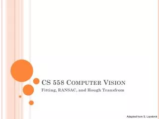
CS 558 Computer Vision. Lecture VIII: Single View and Epipolar Geometry. Slide adapted from S. Lazebnik. Outline. Single view geometry Epiploar geometry. Single-view geometry. Odilon Redon, Cyclops, 1914. X?. X?. X?. Our goal: Recovery of 3D structure.

E N D
CS 558 Computer Vision Lecture VIII: Single View and Epipolar Geometry Slide adapted from S. Lazebnik
Outline • Single view geometry • Epiploar geometry
Single-view geometry Odilon Redon, Cyclops, 1914
X? X? X? Our goal: Recovery of 3D structure • Recovery of structure from one image is inherently ambiguous x
Our goal: Recovery of 3D structure • Recovery of structure from one image is inherently ambiguous
Our goal: Recovery of 3D structure • Recovery of structure from one image is inherently ambiguous
Ames Room http://en.wikipedia.org/wiki/Ames_room
Our goal: Recovery of 3D structure • We will need multi-view geometry
Recall: Pinhole camera model • Principal axis: line from the camera center perpendicular to the image plane • Normalized (camera) coordinate system: camera center is at the origin and the principal axis is the z-axis
Principal point • Principal point (p): point where principal axis intersects the image plane (origin of normalized coordinate system) • Normalized coordinate system: origin is at the principal point • Image coordinate system: origin is in the corner • How to go from normalized coordinate system to image coordinate system? py px
Principal point offset principal point: py px
Principal point offset principal point: calibration matrix
mx pixels per meter in horizontal direction, my pixels per meter in vertical direction Pixel coordinates Pixel size: m pixels pixels/m
Camera rotation and translation • In general, the camera coordinate frame will be related to the world coordinate frame by a rotation and a translation coords. of point in camera frame coords. of camera center in world frame coords. of a pointin world frame (nonhomogeneous)
Camera rotation and translation In non-homogeneouscoordinates: Note: C is the null space of the camera projection matrix (PC=0)
Intrinsic parameters Principal point coordinates Focal length Pixel magnification factors Skew (non-rectangular pixels) Radial distortion Camera parameters
Camera parameters • Intrinsic parameters • Principal point coordinates • Focal length • Pixel magnification factors • Skew (non-rectangular pixels) • Radial distortion • Extrinsic parameters • Rotation and translation relative to world coordinate system
Xi xi Camera calibration • Given n points with known 3D coordinates Xi and known image projections xi, estimate the camera parameters
Camera calibration: Linear method Two linearly independent equations
Camera calibration: Linear method • P has 11 degrees of freedom (12 parameters, but scale is arbitrary) • One 2D/3D correspondence gives us two linearly independent equations • Homogeneous least squares • 6 correspondences needed for a minimal solution
Camera calibration: Linear method • Note: for coplanar points that satisfy ΠTX=0,we will get degenerate solutions (Π,0,0), (0,Π,0), or (0,0,Π)
Camera calibration: Linear method • Advantages: easy to formulate and solve • Disadvantages • Doesn’t directly tell you camera parameters • Doesn’t model radial distortion • Can’t impose constraints, such as known focal length and orthogonality • Non-linear methods are preferred • Define error as difference between projected points and measured points • Minimize error using Newton’s method or other non-linear optimization
Multi-view geometry problems • Structure: Given projections of the same 3D point in two or more images, compute the 3D coordinates of that point ? Camera 1 Camera 3 Camera 2 R1,t1 R3,t3 R2,t2 Slide credit: Noah Snavely
Multi-view geometry problems • Stereo correspondence: Given a point in one of the images, where could its corresponding points be in the other images? Camera 1 Camera 3 Camera 2 R1,t1 R3,t3 R2,t2 Slide credit: Noah Snavely
Multi-view geometry problems • Motion: Given a set of corresponding points in two or more images, compute the camera parameters ? Camera 1 ? Camera 3 ? Camera 2 R1,t1 R3,t3 R2,t2 Slide credit: Noah Snavely
X? x2 x1 O2 O1 Triangulation • Given projections of a 3D point in two or more images (with known camera matrices), find the coordinates of the point
X? x2 x1 O2 O1 Triangulation • We want to intersect the two visual rays corresponding to x1 and x2, but because of noise and numerical errors, they don’t meet exactly R1 R2
Triangulation: Geometric approach • Find shortest segment connecting the two viewing rays and let X be the midpoint of that segment X x2 x1 O2 O1
Triangulation: Linear approach Cross product as matrix multiplication:
Triangulation: Linear approach Two independent equations each in terms of three unknown entries of X
Find X that minimizes Triangulation: Nonlinear approach X? x’1 x2 x1 x’2 O2 O1
Epipolar geometry X x x’ • Baseline – line connecting the two camera centers • Epipolar Plane – plane containing baseline (1D family) • Epipoles • = intersections of baseline with image planes • = projections of the other camera center
The Epipole Photo by Frank Dellaert
Epipolar geometry X x x’ • Baseline – line connecting the two camera centers • Epipolar Plane – plane containing baseline (1D family) • Epipoles • = intersections of baseline with image planes • = projections of the other camera center • Epipolar Lines - intersections of epipolar plane with image planes (always come in corresponding pairs)
Example: Motion perpendicular to image plane e’ e Epipole has same coordinates in both images. Points move along lines radiating from e: “Focus of expansion”
Epipolar constraint X • If we observe a point x in one image, where can the corresponding point x’ be in the other image? x x’
Epipolar constraint X X X x x’ x’ x’ • Potential matches for x have to lie on the corresponding • epipolar line l’. • Potential matches for x’ have to lie on the corresponding • epipolar line l.
Epipolar constraint: Calibrated case X • Assume that the intrinsic and extrinsic parameters of the cameras are known • We can multiply the projection matrix of each camera (and the image points) by the inverse of the calibration matrix to get normalized image coordinates • We can also set the global coordinate system to the coordinate system of the first camera. Then the projection matrix of the first camera is [I | 0]. x x’
Epipolar constraint: Calibrated case X = RX’ + t x x’ t R The vectors x, t, and Rx’ are coplanar
Epipolar constraint: Calibrated case X x x’ Essential Matrix (Longuet-Higgins, 1981) The vectors x, t, and Rx’ are coplanar
Epipolar constraint: Calibrated case X • E x’ is the epipolar line associated with x’ (l = E x’) • ETx is the epipolar line associated with x (l’ = ETx) • E e’ = 0 and ETe = 0 • E is singular (rank two) • E has five degrees of freedom x x’
Epipolar constraint: Uncalibrated case X • The calibration matrices K and K’ of the two cameras are unknown • We can write the epipolar constraint in terms of unknown normalized coordinates: x x’