Download

1 / 28
910 likes | 2.08k Views
Metal Machining. Semester I Session 2013/2014. TOPIC OUTLINE. Introduction Mechanics of Cutting Cutting Conditions Chip Formation Types of Cutting Cutting Tool Materials Tool Wear and Tool Life Cutting Fluid Surface Finish . LESSON OUTCOMES.

E N D
Metal Machining Bachelor of Industrial Technology Management with Honours Semester I Session 2013/2014
TOPIC OUTLINE • Introduction • Mechanics of Cutting • Cutting Conditions • Chip Formation • Types of Cutting • Cutting Tool Materials • Tool Wear and Tool Life • Cutting Fluid • Surface Finish
LESSON OUTCOMES • Able to explain the fundamentals of metal cutting • Able to select appropriate machining operations for producing products with different specifications
INTRODUCTION Classification of Manufacturing Process • Primary Processes - Eg.: Casting, Forging, Molding, etc. • Secondary Processes - Eg.: Machining • Tertiary - Assembly - Eg.: Fabricating like Welding, Brazing, Riveting, etc. • Finishing and Surface Treatment – Aesthetic Look - Eg.: Painting, Electroplating, etc.
INTRODUCTION The place of machining operations within the entire production cycle
MACHINING PROCESS • Machining is a manufacturing process in which sharp cutting tool is used to cut away material to leave the desired part shape • The predominant cutting action in machining involves shear deformation of the work material to form a chip : process of removing unwanted material from a work piece in the form of chips • Performed after other processes which provides final shape, more precise dimensions and smooth surface finishes. • Material removal process – excess material is removed from a starting work part so that what remains is the desired final geometry
Schematic illustrations of various machining and finishing processes. INTRODUCTION
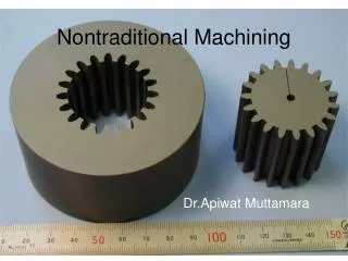
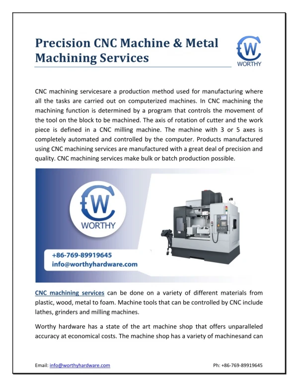
MACHINING PROCESS 3 Categories: Traditional / Conventional – sharp cutting tool is used to mechanically cut the material to achieve the desired geometry : turning, milling and drilling Abrasive – mechanically remove material by the action of hard, abrasive particles : grinding Non-traditional – use various energy forms include mechanical, electrochemical, thermal & chemical : EDM, CNC etc.
MACHINING PROCESS Advantages Disadvantages Wasteful of material Time consuming • Variety of work materials • Variety of part shapes and geometric features • Dimensional accuracy • Good surface finishes
MECHANICS OF CUTTING Major independent variables in cutting process Factors influencing the cutting processes: • Tool material and coatings • Tool shape, surface finish and sharpness • Work piece material and condition • Cutting speed, feed and depth of cut • Cutting fluids & work holding • Characteristics of the machine tool Major dependent variables in cutting process Influenced by the changes in the independent variables: • Types of chip produced • Force and energy distributed during cutting • Temperature rise in the work piece, tool and chip • Tool wear and failure • Surface finish and surface quality of the work piece
MECHANICS OF CUTTING Problems when machining operations yield unacceptable results such as: • Surface finish of the work piece is unacceptable • Cutting tool wears rapidly and becomes dull • Work piece become very hot • Tool begins to vibrate and chatter • Require a systematic investigation – study the mechanics of cutting.
CUTTING CONDITIONS Elements: • Cutting speed, V (shown with heavy dark arrow) • The primary cutting motion. • Travelling velocity of the tool relative to the work piece. • Measured in m/s or m/min. • Feed, f (shown with dashed arrows) • In turning - amount of material removed per revolution of the work piece and measured in mm/rev • In milling and drilling – amount of material removed per pass of the tool over the work piece and measured in mm/min • To machine a large surface, the tool must be given a feed. • Depth of cut, d • The distance the tool is plunged into the surface of the workpiece and measured in mm.
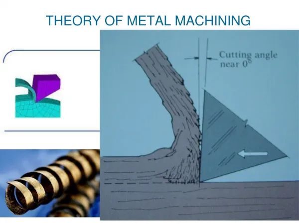
CHIP FORMATION • Diagram shows removal of the deformed material from the work piece by a single point cutting tool. • The movement of the tool into the work piece deforms the work material ahead of the tool face plastically and finally separates the deformed material from the work piece. • This separated material flows on the rake face of the tool called as chip. • The chip near the end of the rake face is lifted away from the tool, and the resultant curvature of the chip is called chip curl.
TYPES OF CHIPS • Continuous chips - looks like a long ribbon with a smooth and continuous shining surface; resulting in good surface finish, high tool life and low power consumption. • Built-up edge - a very hardened layer of work material gradually attached to the tool face; as it grows larger, it becomes unstable and breaks apart, carried away by the tool side and rest on work piece surface. • Discontinuous chips - comes off as small chunks or particles; it indicates brittle work material, work piece materials containing hard inclusions and impurities, very low or high cutting speeds, large depth of cut etc. • Determined by a number of parameter: • Type of tool-work engagement • Work material properties • Cutting conditions
TYPES OF CUTTING Principle Types of Cutting: • Orthogonal Cutting • Cutting edge is straight and is set in a position that is perpendicular to the direction of primary motion and the length of the cutting edge is greater than the width of the chip removed. • Known as Two-Dimensional (2-D) Cutting. • A few of cutting tools perform orthogonally e.g. lathe cut-off tools, straight milling cutters etc.
TYPES OF CUTTING • Oblique Cutting • Cutting edge is set at an angle and inclined to the cutting direction (the tool cutting edge inclination λs). • Known as Three Dimensional (3-D) Cutting. • Majority of the cutting operations perform obliquely such as turning, milling etc.
CUTTING TOOL 2 types: • Single-point cutting • Cutting tool has only one major cutting edge. • Eg.: turning, boring. • Multipoint cutting • Cutting tool has more than one major cutting edge. • Eg.: drilling, milling, reaming
CUTTING TOOL MATERIALS • Must possess properties to avoid excessive wear, fracture failure and high temperatures in cutting. • Required characteristics: • Hardness at elevated temperatures (so-called hot hardness) - so that hardness and strength of the tool edge are maintained in high cutting temperatures.
CUTTING TOOL MATERIALS • Toughness - ability of the material to absorb energy without failing. • Wear resistance - depends on hot hardness, surface finish on the tool, chemical inertness and thermal conductivity of the tool material. Types: • Carbon steels • High-speed steel • Cemented carbides • Ceramics • Cubic Boron Nitride (CBN) • Synthetic Diamonds
TOOL WEAR AND TOOL LIFE Categories of tool wear: • Gradual wearing of certain regions of the face and flank of the cutting tool • Abrupt tool failure Options of resolving tool wear: • Re-sharpen the tool on a tool grinder, or • Replace the tool with a new one and applied when: • Resource for tool resharpening is exhausted • Tool does not allow for resharpening
TOOL WEAR AND TOOL LIFE Parameters which affect the rate of tool wear: • Cutting conditions (cutting speed V, feed f, depth of cut d) • Cutting tool geometry (tool orthogonal rake angle) • Cutting fluids Measures to reduce the tool wear: • Appropriate setting of cutting conditions • Application of advance cutting tool materials (coated carbide, ceramics) • Use of cutting fluid
CUTTING FLUID • Any liquid or gas that is applied to the chip and/or cutting tool to improve cutting performance. • Main functions: • Remove heat in cutting • Depends on the method of application, type of the cutting fluid and the fluid flow rate and pressure. • Lubricate the chip-tool interface • Cutting fluids penetrate the tool-chip interface and reducing the friction forces and temperatures. • Wash away chips • Applicable to small, discontinuous chips only. • Special devices are subsequently needed to separate chips from cutting fluids. • Types: • Cutting oils • Soluble oils • Chemical fluids
CUTTING FLUID Schematic illustration of the methods of applying cutting fluids (by flooding) in various machining operations: (a) turning, (b) milling, (c) thread grinding, and (d) drilling.
SURFACE FINISH Machining processes generate a wide variety of surface textures. Types of surface texture: • Roughness - small, finely spaced surface irregularities (micro irregularities) • Waviness - surface irregularities of grater spacing (macro irregularities) • Lay - predominant direction of surface texture
SURFACE FINISH Factors influencing surface roughness: • Tool geometry (major cutting edge angle and tool corner radius) - Increasing the tool rake angle improves surface finish. • Cutting conditions (cutting velocity and feed) - High speed and low feed provide best surface finish. • Work material properties (hardness) - Higher work material hardness results in better surface finish. - Tool material has minor effect on surface finish. • Cutting fluid - Cutting fluids affect the surface finish by changing cutting temperature.