Download
1 / 11
110 likes | 153 Views
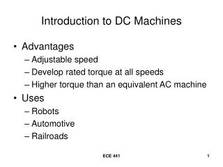
Learn about the essential elements of armature windings in DC machines, including turns, coils, winding types, and pole connections. Explore lap winding and wave winding techniques to understand coil configurations and connections for efficient machine operation.

E N D
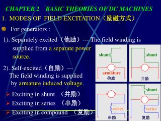
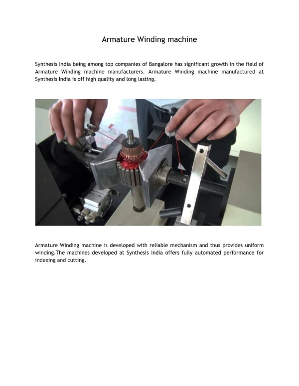
Elements of an armature windings A turn – two conductors connected to an end by an end connector
Elements of an armature windings A coil – several turns connected in series
Elements of an armature windings A winding – several coils connected in series
180o electrical = 90o mech 360o electrical = 180o mech Elements of an armature windings The angle between centers of adjacent poles is 180o (electrical) N S S N
a a b b Elements of an armature windings The angle between centers of adjacent poles is 180o (electrical) If coil sides are placed 180o electrical apart, the coil is said to be full-pitch N 180oelec S S N
Elements of an armature windings The most common ways of connecting coils for armature windings: Lap winding Wave winding Ends of the coils are connected to the commutator bars In DC machines most of the coils are full-pitch.
Commutator bar Elements of an armature windings Lap winding • One coil between adjacent commutator bars • 1/p of total coils are connected in series • No. of poles no. of brushes no. of parallel paths
Elements of an armature windings Wave winding • p/2 coils in series between adjacent commutator bars • ½ of all coils between brushes • Regardless of no. of poles, there are always 2 parallel path • The distance between end coils (commutator pitch) is 2(C1)/p where C is the no. of commutator bars