Download
1 / 32
0 likes | 18 Views
To get the complete manual, please open the home page website.<br><br>https://www.aservicemanualpdf.com/

E N D
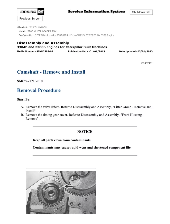
970F Wheel Loader 7SK00224-UP (MACHINE) POWERED BY 3306 Engine(SEBP... 1/5 Shutdown SIS Previous Screen Product: WHEEL LOADER Model: 970F WHEEL LOADER 7SK Configuration: 970F Wheel Loader 7SK00224-UP (MACHINE) POWERED BY 3306 Engine Disassembly and Assembly 3304B and 3306B Engines for Caterpillar Built Machines Media Number -SENR5598-09 Publication Date -01/01/2013 Date Updated -25/01/2013 i01037991 Camshaft - Remove and Install SMCS - 1210-010 Removal Procedure Start By: A. Remove the valve lifters. Refer to Disassembly and Assembly, "Lifter Group - Remove and Install". B. Remove the timing gear cover. Refer to Disassembly and Assembly, "Front Housing - Remove". NOTICE Keep all parts clean from contaminants. Contaminants may cause rapid wear and shortened component life. https://127.0.0.1/sisweb/sisweb/techdoc/techdoc_print_page.jsp?returnurl=/sis... 2021/11/11
970F Wheel Loader 7SK00224-UP (MACHINE) POWERED BY 3306 Engine(SEBP... 2/5 Illustration 1 g00476744 1. Turn the crankshaft to top center compression stroke for the No. 1 piston. The "C" mark on the crankshaft gear will be aligned with the "C" mark on the camshaft gear. Illustration 2 g00476743 Note: Put a mark on the teeth of the fuel injection pump drive gear and the idler gear at location (A). This will help to keep the engine timing correct during the removal and the installation of the camshaft. Put a mark on the teeth of the idler gear and camshaft gear (2) at location (B). When the camshaft is installed, the engine timing will be correct when the mark at location (A) is aligned with the mark at location (B) and the "C" mark on the crankshaft gear is aligned with the "C" mark on the camshaft gear. 2. Remove the bolts, the lock and washer (1) . Illustration 3 g00535590 https://127.0.0.1/sisweb/sisweb/techdoc/techdoc_print_page.jsp?returnurl=/sis... 2021/11/11
970F Wheel Loader 7SK00224-UP (MACHINE) POWERED BY 3306 Engine(SEBP... 3/5 NOTICE Do not damage the lobes or the bearings when the camshaft is removed. 3. Carefully remove camshaft (3) from the engine. 4. If necessary, remove the bolts that hold camshaft drive gear (2) to the camshaft and remove the gear. Installation Procedure NOTICE Keep all parts clean from contaminants. Contaminants may cause rapid wear and shortened component life. Illustration 4 g00535590 1. Put camshaft drive gear (2) in position on the end of camshaft (3). Install the bolts that hold camshaft drive gear (2) to camshaft (3). Tighten the bolts to a torque of 55 ± 7 N·m (41 ± 5 lb ft). NOTICE Do not damage the lobes or the bearings when the camshaft is installed. https://127.0.0.1/sisweb/sisweb/techdoc/techdoc_print_page.jsp?returnurl=/sis... 2021/11/11
970F Wheel Loader 7SK00224-UP (MACHINE) POWERED BY 3306 Engine(SEBP... 4/5 2. Put 8T-2998 Camshaft Lubricant on the camshaft lobes only and put clean engine oil on the bearing journals. Note: During the installation of camshaft (3), rotate the camshaft in both directions in order to prevent binding in the camshaft bearing bores. 3. Carefully install camshaft (3) into the engine. Illustration 5 g00476743 Illustration 6 g00476744 4. Make sure that the mark on the teeth of the fuel injection pump drive gear and the idler gear are in alignment at location (A). Make sure that the mark on the teeth of the idler gear and camshaft gear (2) are in alignment at location (B). Align the "C" marks on the crankshaft gear and camshaft gear (2). When all of the timing marks are in alignment the engine timing is correct. https://127.0.0.1/sisweb/sisweb/techdoc/techdoc_print_page.jsp?returnurl=/sis... 2021/11/11
970F Wheel Loader 7SK00224-UP (MACHINE) POWERED BY 3306 Engine(SEBP... 5/5 5. Install washer (1), the lock and the two bolts that hold the camshaft in position in the engine. End By: a. Install the valve lifters. Refer to Disassembly and Assembly, "Lifter Group - Remove and Install". b. Install the timing gear cover. Refer to Disassembly and Assembly, "Front Housing - Install". Copyright 1993 - 2021 Caterpillar Inc. Thu Nov 11 16:02:04 UTC+0800 2021 All Rights Reserved. Private Network For SIS Licensees. https://127.0.0.1/sisweb/sisweb/techdoc/techdoc_print_page.jsp?returnurl=/sis... 2021/11/11
https://www.aservicemanualpdf.com/ My Dear Friend! Thank you very much for visiting. Full manual if required, please enter the following URL into your browser. https://www.aservicemanualpdf.com/
970F Wheel Loader 7SK00224-UP (MACHINE) POWERED BY 3306 Engine(SEBP... 1/4 Shutdown SIS Previous Screen Product: WHEEL LOADER Model: 970F WHEEL LOADER 7SK Configuration: 970F Wheel Loader 7SK00224-UP (MACHINE) POWERED BY 3306 Engine Disassembly and Assembly 3304B and 3306B Engines for Caterpillar Built Machines Media Number -SENR5598-09 Publication Date -01/01/2013 Date Updated -25/01/2013 i02473351 Camshaft Bearings - Remove and Install SMCS - 1211-010 Removal Procedure Table 1 Required Tools Tool Part Number Part Description Qty 8S-2241 Camshaft Bearing Tool Group 1 A 8H-0684 Ratchet Wrench 1 Start By: A. Remove the Flywheel Housing. Refer to Disassembly and Assembly, "Flywheel Housing - Remove and Install". B. Remove the Oil Pan Plate. Refer to Disassembly and Assembly, "Oil Pan Plate - Remove and Install". C. Remove the Camshaft. Refer to Disassembly and Assembly, "Camshaft - Remove and Install". NOTICE Keep all parts clean from contaminants. Contaminants may cause rapid wear and shortened component life. https://127.0.0.1/sisweb/sisweb/techdoc/techdoc_print_page.jsp?returnurl=/sis... 2021/11/11
970F Wheel Loader 7SK00224-UP (MACHINE) POWERED BY 3306 Engine(SEBP... 2/4 Illustration 1 g00478567 1. Use Tool (A) to remove the camshaft bearing from the cylinder block. Start with the front bearings and work to the rear bearing. Installation Procedure Table 2 Required Tools Tool Part Number Part Description Qty 8S-2241 Camshaft Bearing Tool Group 1 A 8H-0684 Ratchet Wrench 1 NOTICE Keep all parts clean from contaminants. Contaminants may cause rapid wear and shortened component life. https://127.0.0.1/sisweb/sisweb/techdoc/techdoc_print_page.jsp?returnurl=/sis... 2021/11/11
970F Wheel Loader 7SK00224-UP (MACHINE) POWERED BY 3306 Engine(SEBP... 3/4 Illustration 2 g00478567 1. Use Tool (A) to install the camshaft bearings in the 3304B and 3306B cylinder block. Note: The camshaft bearings in the 3304B have pressure lubrication. The intermediate camshaft bearings and the rear camshaft bearings in the 3306B have splash lubrication. 2. Install the camshaft bearings in the 3304B cylinder block, as follows: (a) Install the front bearing to a depth of 0.57 ± 0.5 mm (0.022 ± 0.02 inch). Ensure that the oil holes are in a horizontal position and that the camshaft bearing joint is at the top of the engine. The camshaft bearing joint can not be more than 15° degrees from vertical in either direction. (b) Install the center bearing to a depth of 303.2 ± 0.5 mm (11.94 ± 0.02 inch). Ensure that the oil holes in the camshaft bearing are in alignment with the oil holes in the cylinder block. (c) Install the rear bearing to a depth of 604.9 ± 0.5 mm (23.81 ± 0.02 inch). Ensure that the oil holes in the camshaft bearing are in alignment with the oil holes in the cylinder block. Illustration 3 g00478822 1. Install the camshaft bearings in the 3306B cylinder block, as follows: 2. Install front bearing (B) to a depth of 0.5 ± 0.5 mm (.02 ± .02 inch). Ensure that the oil holes are in a horizontal position and that the camshaft bearing joint is at the top of the engine. The camshaft bearing joint cannot be more than 15 degrees from the vertical position in either direction. 3. Install the remainder of the bearings. Install the bearings to the dimensions that are given from the front face of the cylinder block: (C) 154.0 ± 0.5 mm (6.06 ± .02 inch), (D) 303.2 ± https://127.0.0.1/sisweb/sisweb/techdoc/techdoc_print_page.jsp?returnurl=/sis... 2021/11/11
970F Wheel Loader 7SK00224-UP (MACHINE) POWERED BY 3306 Engine(SEBP... 4/4 0.5 mm (11.94 ± .02 inch), (E) 601.7 ± 0.5 mm (23.69 ± .02 inch) and (F) 903.4 ± 0.5 mm (35.57 ± .02 inch). End By: a. Install the camshaft. Refer to Disassembly and Assembly, "Camshaft - Remove and Install". b. Install the oil pan plate. Refer to Disassembly and Assembly, "Engine Oil Pan Plate - Remove and Install". c. Install the flywheel housing. Refer to Disassembly and Assembly, "Flywheel Housing - Remove and Install". Copyright 1993 - 2021 Caterpillar Inc. Thu Nov 11 16:03:00 UTC+0800 2021 All Rights Reserved. Private Network For SIS Licensees. https://127.0.0.1/sisweb/sisweb/techdoc/techdoc_print_page.jsp?returnurl=/sis... 2021/11/11
970F Wheel Loader 7SK00224-UP (MACHINE) POWERED BY 3306 Engine(SEBP... 1/3 Shutdown SIS Previous Screen Product: WHEEL LOADER Model: 970F WHEEL LOADER 7SK Configuration: 970F Wheel Loader 7SK00224-UP (MACHINE) POWERED BY 3306 Engine Disassembly and Assembly 3304B and 3306B Engines for Caterpillar Built Machines Media Number -SENR5598-09 Publication Date -01/01/2013 Date Updated -25/01/2013 i00974130 Engine Oil Pan - Remove and Install SMCS - 1302-010 Removal Procedure NOTICE Keep all parts clean from contaminants. Contaminants may cause rapid wear and shortened component life. NOTICE Care must be taken to ensure that fluids are contained during performance of inspection, maintenance, testing, adjusting and repair of the machine. Be prepared to collect the fluid with suitable containers before opening any compartment or disassembling any component containing fluids. Refer to Special Publication, NENG2500, "Caterpillar Tools and Shop Products Guide", for tools and supplies suitable to collect and contain fluids in Caterpillar machines. Dispose of all fluids according to local regulations and mandates. 1. Drain the engine oil from the engine into a suitable container for storage or disposal. https://127.0.0.1/sisweb/sisweb/techdoc/techdoc_print_page.jsp?returnurl=/sis... 2021/11/11
970F Wheel Loader 7SK00224-UP (MACHINE) POWERED BY 3306 Engine(SEBP... 2/3 Illustration 1 g00541041 2. Loosen nut (4) and move the overflow tube away from the oil level gauge guide. Loosen nut (3) and remove the oil level gauge guide from the engine. 3. Remove bolts (1) and the washers that hold the engine oil pan in position. Remove engine oil pan (2) and the gasket from the engine oil pan plate. Installation Procedure NOTICE Keep all parts clean from contaminants. Contaminants may cause rapid wear and shortened component life. Illustration 2 g00541041 1. Put the gasket and engine oil pan (2) in position on the engine oil pan plate. Install bolts (1) and the washers that hold the engine oil pan in position. https://127.0.0.1/sisweb/sisweb/techdoc/techdoc_print_page.jsp?returnurl=/sis... 2021/11/11
970F Wheel Loader 7SK00224-UP (MACHINE) POWERED BY 3306 Engine(SEBP... 3/3 2. Install the oil level gauge guide and tighten nut (3). Fasten the overflow tube to the oil level gauge guide and tighten nut (4) . 3. Fill the crankcase with engine oil to the proper level. Refer to Operation and Maintenance Manual, "Refill Capacities". Copyright 1993 - 2021 Caterpillar Inc. Thu Nov 11 16:03:57 UTC+0800 2021 All Rights Reserved. Private Network For SIS Licensees. https://127.0.0.1/sisweb/sisweb/techdoc/techdoc_print_page.jsp?returnurl=/sis... 2021/11/11
970F Wheel Loader 7SK00224-UP (MACHINE) POWERED BY 3306 Engine(SEBP... 1/3 Shutdown SIS Previous Screen Product: WHEEL LOADER Model: 970F WHEEL LOADER 7SK Configuration: 970F Wheel Loader 7SK00224-UP (MACHINE) POWERED BY 3306 Engine Disassembly and Assembly 3304B and 3306B Engines for Caterpillar Built Machines Media Number -SENR5598-09 Publication Date -01/01/2013 Date Updated -25/01/2013 i01111802 Engine Balancer Shaft - Remove and Install SMCS - 1220-010-JF Removal Procedure Start By: A. Remove the front housing cover. Refer to Disassembly and Assembly, "Front Housing Cover - Remove". B. Remove the engine oil pump. Refer to Disassembly and Assembly, "Engine Oil Pump - Remove". NOTICE Keep all parts clean from contaminants. Contaminants may cause rapid wear and shortened component life. NOTICE Care must be taken to ensure that fluids are contained during performance of inspection, maintenance, testing, adjusting and repair of the product. Be prepared to collect the fluid with suitable containers before opening any compartment or disassembling any component containing fluids. Refer to Special Publication, NENG2500, "Caterpillar Tools and Shop Products Guide" for tools and supplies suitable to collect and contain fluids on Caterpillar products. https://127.0.0.1/sisweb/sisweb/techdoc/techdoc_print_page.jsp?returnurl=/sis... 2021/11/11
970F Wheel Loader 7SK00224-UP (MACHINE) POWERED BY 3306 Engine(SEBP... 2/3 Dispose of all fluids according to local regulations and mandates. Note: The oil pan plate has been removed for photo purposes only. Illustration 1 g00590442 1. Remove plates (2) that hold the balancer shaft in the cylinder block. 2. Remove balancer shafts (1) from the cylinder block. Installation Procedure Illustration 2 g00590449 NOTICE Keep all parts clean from contaminants. Contaminants may cause rapid wear and shortened component life. https://127.0.0.1/sisweb/sisweb/techdoc/techdoc_print_page.jsp?returnurl=/sis... 2021/11/11
970F Wheel Loader 7SK00224-UP (MACHINE) POWERED BY 3306 Engine(SEBP... 3/3 1. Install the balancer shafts in each side of the cylinder block. 2. Install plates (2) and the bolts that hold the balancer shafts in position in the cylinder block. Note: Ensure that the balancer shafts are in time before the oil pump is installed. End By: a. Install the engine oil pump. Refer to Disassembly and Assembly, "Engine Oil Pump - Install". b. Install the front housing cover. Refer to Disassembly and Assembly, "Front Housing Cover - Install". Copyright 1993 - 2021 Caterpillar Inc. Thu Nov 11 16:04:54 UTC+0800 2021 All Rights Reserved. Private Network For SIS Licensees. https://127.0.0.1/sisweb/sisweb/techdoc/techdoc_print_page.jsp?returnurl=/sis... 2021/11/11
970F Wheel Loader 7SK00224-UP (MACHINE) POWERED BY 3306 Engine(SEBP... 1/4 Shutdown SIS Previous Screen Product: WHEEL LOADER Model: 970F WHEEL LOADER 7SK Configuration: 970F Wheel Loader 7SK00224-UP (MACHINE) POWERED BY 3306 Engine Disassembly and Assembly 3304B and 3306B Engines for Caterpillar Built Machines Media Number -SENR5598-09 Publication Date -01/01/2013 Date Updated -25/01/2013 i01135419 Engine Balancer Shaft Bearings - Remove and Install SMCS - 1220-010-BD Removal Procedure Table 1 Required Tools Tool Part Number Part Description Qty 8S-2241 Camshaft Bearing Tool Group 1 A 8H-0684 Ratchet Wrench 1 Start By: A. Remove the engine oil pan. Refer to Disassembly and Assembly, "Engine Oil Pan - Remove". B. Remove the balancer shaft. Refer toDisassembly and Assembly, "Balancer Shaft - Remove". C. Remove the flywheel housing. Refer to Disassembly and Assembly, "Flywheel Housing Remove" . NOTICE Keep all parts clean from contaminants. Contaminants may cause rapid wear and shortened component life. NOTICE https://127.0.0.1/sisweb/sisweb/techdoc/techdoc_print_page.jsp?returnurl=/sis... 2021/11/11
970F Wheel Loader 7SK00224-UP (MACHINE) POWERED BY 3306 Engine(SEBP... 2/4 Care must be taken to ensure that fluids are contained during performance of inspection, maintenance, testing, adjusting and repair of the product. Be prepared to collect the fluid with suitable containers before opening any compartment or disassembling any component containing fluids. Refer to Special Publication, NENG2500, "Caterpillar Tools and Shop Products Guide" for tools and supplies suitable to collect and contain fluids on Caterpillar products. Dispose of all fluids according to local regulations and mandates. Illustration 1 g00602186 Use Tool (A) to remove the six balancer shaft bearing. Pull the balancer shaft bearings toward the flywheel end of the engine. Installation Procedure Illustration 2 g00602186 https://127.0.0.1/sisweb/sisweb/techdoc/techdoc_print_page.jsp?returnurl=/sis... 2021/11/11
970F Wheel Loader 7SK00224-UP (MACHINE) POWERED BY 3306 Engine(SEBP... 3/4 Illustration 3 g00602205 (A) The front bearing depth is 0.8 ± 0.5 mm (0.03 ± 0.02 inch). (B) The center bearing depth is 290.6 ± 0.5 mm (11.44 ± 0.02 inch). (C) The rear bearing depth is 601.0 ± 0.5 mm (23.66 ± 0.02 inch). NOTICE Keep all parts clean from contaminants. Contaminants may cause rapid wear and shortened component life. NOTICE Care must be taken to ensure that fluids are contained during performance of inspection, maintenance, testing, adjusting and repair of the product. Be prepared to collect the fluid with suitable containers before opening any compartment or disassembling any component containing fluids. Refer to Special Publication, NENG2500, "Caterpillar Tools and Shop Products Guide" for tools and supplies suitable to collect and contain fluids on Caterpillar products. Dispose of all fluids according to local regulations and mandates. https://127.0.0.1/sisweb/sisweb/techdoc/techdoc_print_page.jsp?returnurl=/sis... 2021/11/11
970F Wheel Loader 7SK00224-UP (MACHINE) POWERED BY 3306 Engine(SEBP... 4/4 1. Install the balancer shaft front bearing with Tool (A). Ensure that the holes in the bearings are aligned with the holes in the cylinder block. The bearing must be 0.8 ± 0.5 mm (0.03 ± 0.02 inch) inside the front face of the cylinder block after installation. 2. Install the balancer shaft center bearing with Tool (A). Ensure that the holes in the bearings are aligned with the holes in the cylinder block. The bearing must be 290.6 ± 0.5 mm (11.44 ± 0.02 inch) inside the front face of the cylinder block after installation. 3. Install the balancer shaft rear bearing with Tool (A). Ensure that the holes in the bearings are aligned with the holes in the cylinder block. The bearing must be 601.0 ± 0.5 mm (23.66 ± 0.02 inch) inside the front face of the cylinder block after installation. 4. Check the bore of the bearings. The balancer shaft bearing bore must be 53.05 ± 0.06 mm (2.089 ± 0.002 inch) after installation. End By: a. Install the flywheel housing. Refer to Disassembly and Assembly, "Flywheel Housing - Install" . b. Install the balancer shaft. Refer to Disassembly and Assembly, "Balancer Shaft - Remove and Install". c. Install the engine oil pan. Refer to Disassembly and Assembly, "Engine Oil Pan - Remove and Install". Copyright 1993 - 2021 Caterpillar Inc. Thu Nov 11 16:05:51 UTC+0800 2021 All Rights Reserved. Private Network For SIS Licensees. https://127.0.0.1/sisweb/sisweb/techdoc/techdoc_print_page.jsp?returnurl=/sis... 2021/11/11
970F Wheel Loader 7SK00224-UP (MACHINE) POWERED BY 3306 Engine(SEBP... 1/2 Shutdown SIS Previous Screen Product: WHEEL LOADER Model: 970F WHEEL LOADER 7SK Configuration: 970F Wheel Loader 7SK00224-UP (MACHINE) POWERED BY 3306 Engine Disassembly and Assembly 3304B and 3306B Engines for Caterpillar Built Machines Media Number -SENR5598-09 Publication Date -01/01/2013 Date Updated -25/01/2013 i00912474 Cylinder Liner - Remove SMCS - 1216-011 Removal Procedure Table 1 Required Tools Tool Part Number Part Description Qty 8T-0812 Cylinder Liner Puller 1 A 1U-6317 Bridge 1 1U-6319 Socket 1 Start By: A. Remove the spacer plate. Refer to Disassembly and Assembly, "Spacer Plate - Remove and Install". B. Remove the engine oil pump. Refer to Disassembly and Assembly, "Engine Oil Pump - Remove". NOTICE Keep all parts clean from contaminants. Contaminants may cause rapid wear and shortened component life. https://127.0.0.1/sisweb/sisweb/techdoc/techdoc_print_page.jsp?returnurl=/sis... 2021/11/11
970F Wheel Loader 7SK00224-UP (MACHINE) POWERED BY 3306 Engine(SEBP... 2/2 Illustration 1 g00474523 1. Turn the crankshaft until two of the pistons are at the bottom center. Remove two connecting rod cap bolts (2) from each rod. Remove connecting rod caps (4) . 2. Tap connecting rod (3) away from the crankshaft with a soft hammer. Remove bearing half (1) . Illustration 2 g00474623 3. Use tool (A) to remove cylinder liners (5) . 4. Remove the pistons and connecting rods from the cylinder liners. Copyright 1993 - 2021 Caterpillar Inc. Thu Nov 11 16:06:47 UTC+0800 2021 All Rights Reserved. Private Network For SIS Licensees. https://127.0.0.1/sisweb/sisweb/techdoc/techdoc_print_page.jsp?returnurl=/sis... 2021/11/11
970F Wheel Loader 7SK00224-UP (MACHINE) POWERED BY 3306 Engine(SEBP... 1/5 Shutdown SIS Previous Screen Product: WHEEL LOADER Model: 970F WHEEL LOADER 7SK Configuration: 970F Wheel Loader 7SK00224-UP (MACHINE) POWERED BY 3306 Engine Disassembly and Assembly 3304B and 3306B Engines for Caterpillar Built Machines Media Number -SENR5598-09 Publication Date -01/01/2013 Date Updated -25/01/2013 i01048841 Cylinder Liner - Install SMCS - 1216-012 Installation Procedure Table 1 Required Tools Tool Part Number Part Description Qty A 8T-0455 Liner Projection Tool 1 B 2P-8260 Cylinder Liner Installation Tool 1 Note: The following procedure alleviates the need for the crossbar to hold the cylinder liners during cylinder liner projection measurements. 1. Clean the cylinder liner flange and the cylinder block surface. Remove any nicks on the top of the cylinder block. 2. Install clean cylinder liners without the rubber seals or the filler band. Install a new spacer plate gasket and the clean spacer plate. Table 2 Required Components Item Part Part Quantity For One Cylinder Quantity For Six Cylinders Number Description 1 0S-1589 Bolt 6 36 2 2S-0736 Washer 6 36 3 8F-1484 Washer 6 36 4 7K-1977 Washer 6 36 https://127.0.0.1/sisweb/sisweb/techdoc/techdoc_print_page.jsp?returnurl=/sis... 2021/11/11
970F Wheel Loader 7SK00224-UP (MACHINE) POWERED BY 3306 Engine(SEBP... 2/5 Illustration 1 g00544054 3. Install the bolts and washers in the order that is shown in Illustration 1 in order to seat the cylinder liner in the block. Tighten bolts (1) evenly to a torque of 95 N·m (70 lb ft). Illustration 2 g00544478 (5) Bolt (6) Dial Indicator (7) Gauge Body (8) Gauge https://127.0.0.1/sisweb/sisweb/techdoc/techdoc_print_page.jsp?returnurl=/sis... 2021/11/11
970F Wheel Loader 7SK00224-UP (MACHINE) POWERED BY 3306 Engine(SEBP... 3/5 4. Loosen bolt (5) until dial indicator (6) can be moved. Place gauge body (7) and dial indicator (6) on the long side of gauge (8) . 5. Slide dial indicator (6) into position until the point contacts gauge (8). Slide dial indicator (6) until the needle of the dial indicator makes a quarter of a revolution clockwise. The needle should be in a vertical position. Tighten bolt (5) and zero dial indicator (6) . 6. Place gauge body (7) on the spacer plate with the dial indicator point on the cylinder liner flange. Read the dial indicator in order to find the amount of liner projection. Check the liner projection at four locations (every 90 degrees) around each cylinder liner. Table 3 Specifications Liner Projection 0.033 mm (.0013 inch) to 0.175 mm (.0069 inch) Maximum Variation in Each Cylinder 0.051 mm (.0020 inch) Maximum Average Variation Between Adjacent Cylinders 0.051 mm (.0020 inch) Maximum Variation Between All Cylinders 0.102 mm (.0040 inch) 7. If the cylinder liner projection is out of specification, rotate the cylinder liner in the bore and repeat the procedure. If the cylinder liner projection measurements are again out of specification, try installing the cylinder liner in a different cylinder bore to improve the measurements. Note: Do not exceed the maximum liner projection of 0.175 mm (0.0069 inch). Cracking in the flange of the cylinder liner results from excessive cylinder liner projection measurements. 8. If the maximum variation between cylinder liners is greater than the recommended specification, shims must be used in order to reach the correct specification. 9. When the cylinder liner projection for each cylinder liner is within the recommended specification, mark each cylinder liner for the proper location in the bore and remove the cylinder liners. 10. Lubricate the O-ring seals, the cylinder liner, and the upper filler band before installation. Note: If the lower O-ring seals are black in color, apply liquid soap on the lower O-ring seals and the cylinder block. Use clean engine oil on the upper filler band. Note: If the lower O-rings are brown in color, apply engine oil on the lower O-ring seals, the cylinder block, and the upper filler band. NOTICE https://127.0.0.1/sisweb/sisweb/techdoc/techdoc_print_page.jsp?returnurl=/sis... 2021/11/11
970F Wheel Loader 7SK00224-UP (MACHINE) POWERED BY 3306 Engine(SEBP... 4/5 Apply 5P-3975 Rubber Lubricant and/or clean engine oil immediately before assembly. If the 5P-3975 Rubber Lubricant or engine oil is applied too early, the filler bands and/or O-ring seals may swell and the filler bands and/or O-ring seals may be pinched under the cylinder liner during installation. Illustration 3 g00544889 11. Apply liquid soap on the bottom cylinder liner bore in the cylinder block. Apply liquid soap on the grooves of the cylinder liner and on O-ring seals (4). Install O-ring seals (4) on the cylinder liner. 12. Lubricate filler band (5) with clean engine oil and install filler band (5) on cylinder liner (6). Install cylinder liner (6) into the engine block immediately after you lubricate the cylinder liner. This helps to prevent swelling of the filler band. Illustration 4 g00478920 13. Ensure that the mark on the cylinder liner is in alignment with the mark on the cylinder block. Use Tool (B) to press each of the cylinder liners into position. End By: https://127.0.0.1/sisweb/sisweb/techdoc/techdoc_print_page.jsp?returnurl=/sis... 2021/11/11
Please write to us. Our email: aservicemanualpdf@yahoo.com Please go to the homepage to get the full manual, or other brand PDF manuals. Home Site: aservicemanualpdf.com
GET MORE OTHER MANUALS https://www.aservicemanualpdf.com/ Thank you very much for your reading. Please Click Here. Then Get COMPLETE MANUAL. NO WAITING NOTE: If there is no response to click on the link above, please download the PDF document first and then click on it. GET MORE OTHER MANUALS https://www.aservicemanualpdf.com/
970F Wheel Loader 7SK00224-UP (MACHINE) POWERED BY 3306 Engine(SEBP... 5/5 a. Install the Pistons and Connecting Rods. Refer to Disassembly and Assembly, "Pistons and Connecting Rods - Install". b. Install the cylinder head. Refer to Disassembly and Assembly, "Spacer Plate - Remove and Install". Copyright 1993 - 2021 Caterpillar Inc. Thu Nov 11 16:07:44 UTC+0800 2021 All Rights Reserved. Private Network For SIS Licensees. https://127.0.0.1/sisweb/sisweb/techdoc/techdoc_print_page.jsp?returnurl=/sis... 2021/11/11
970F Wheel Loader 7SK00224-UP (MACHINE) POWERED BY 3306 Engine(SEBP... 1/3 Shutdown SIS Previous Screen Product: WHEEL LOADER Model: 970F WHEEL LOADER 7SK Configuration: 970F Wheel Loader 7SK00224-UP (MACHINE) POWERED BY 3306 Engine Disassembly and Assembly 3304B and 3306B Engines for Caterpillar Built Machines Media Number -SENR5598-09 Publication Date -01/01/2013 Date Updated -25/01/2013 i01112806 Piston Cooling Jets - Remove and Install SMCS - 1331-010 Removal Procedure Start By: A. Remove the crankshaft. Refer to Disassembly and Assembly, "Crankshaft - Remove". NOTICE Keep all parts clean from contaminants. Contaminants may cause rapid wear and shortened component life. Illustration 1 g00473474 https://127.0.0.1/sisweb/sisweb/techdoc/techdoc_print_page.jsp?returnurl=/sis... 2021/11/11
970F Wheel Loader 7SK00224-UP (MACHINE) POWERED BY 3306 Engine(SEBP... 2/3 1. Use a soft punch to remove piston cooling jet (1) from the cylinder block. Installation Procedure Table 1 Required Tools Tool Part Number Part Description Qty A 6V-7772 Driver 1 NOTICE Keep all parts clean from contaminants. Contaminants may cause rapid wear and shortened component life. Note: On the 3304B, the piston cooling jets are installed in the No. 2 and the No. 4 main bosses. On the 3306B, the No. 2 and the No. 6 bosses for the main bearings have two jets. The No. 3 and No. 5 bosses for the main bearings have one jet. A replacement is necessary if the jets are damaged. Normally, it will only be necessary to ensure that the jets are clean. Illustration 2 g00473474 1. Use Tool (A) to install piston cooling jet (1) with the small end first. Install the jets in the bosses for the main bearing until the jets are against the counterbore. 2. Ensure that the passage is open after piston cooling jet (1) is installed. End By: Install the crankshaft. Refer to Disassembly and Assembly, "Crankshaft - Install". Copyright 1993 - 2021 Caterpillar Inc. Thu Nov 11 16:08:41 UTC+0800 2021 All Rights Reserved. https://127.0.0.1/sisweb/sisweb/techdoc/techdoc_print_page.jsp?returnurl=/sis... 2021/11/11
https://www.aservicemanualpdf.com/ My Dear Friend! Thank you very much for visiting. Full manual if required, please enter the following URL into your browser. https://www.aservicemanualpdf.com/