Download
1 / 39
0 likes | 9 Views
shui0151$0

E N D
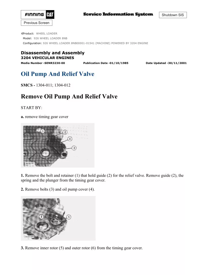
926 WHEEL LOADER 8NB00001-01541 (MACHINE) POWERED BY 3204 ENGI... 1/4 Shutdown SIS Previous Screen Product: WHEEL LOADER Model: 926 WHEEL LOADER 8NB Configuration: 926 WHEEL LOADER 8NB00001-01541 (MACHINE) POWERED BY 3204 ENGINE Disassembly and Assembly 3204 VEHICULAR ENGINES Media Number -SENR3230-00 Publication Date -01/10/1985 Date Updated -30/11/2001 Oil Pump And Relief Valve SMCS - 1304-011; 1304-012 Remove Oil Pump And Relief Valve START BY: a. remove timing gear cover 1. Remove the bolt and retainer (1) that hold guide (2) for the relief valve. Remove guide (2), the spring and the plunger from the timing gear cover. 2. Remove bolts (3) and oil pump cover (4). 3. Remove inner rotor (5) and outer rotor (6) from the timing gear cover. https://127.0.0.1/sisweb/sisweb/techdoc/techdoc_print_page.jsp?returnurl=/sis... 2021/2/17
926 WHEEL LOADER 8NB00001-01541 (MACHINE) POWERED BY 3204 ENGI... 2/4 4. Remove bearing (7) and shaft (8) from the timing gear cover if a replacement is necessary. Install Oil Pump And Relief Valve https://127.0.0.1/sisweb/sisweb/techdoc/techdoc_print_page.jsp?returnurl=/sis... 2021/2/17
926 WHEEL LOADER 8NB00001-01541 (MACHINE) POWERED BY 3204 ENGI... 3/4 1. Install shaft (2) in the timing gear cover until dimension (Y) is 21.84 ± 0.25 mm (.860 ± .010 in.). 2. Use tooling (B) to install bearing (1) in the timing gear cover until dimension (X) is 8.74 ± 0.25 mm (.344 ± .010 in.). Also, the bearing joint must be located 45° ± 30° from centerline (Z). 3. After installation of the bearing in the timing gear cover, check the inside diameter. The inside diameter (W) of the bearing must be 71.22 ± 0.05 (2.804 ± .002 in.). NOTICE When the outer and inner rotors are replaced, they must be replaced as a set. 4. Install outer rotor (4) and inner rotor (3) in the timing gear cover. https://127.0.0.1/sisweb/sisweb/techdoc/techdoc_print_page.jsp?returnurl=/sis... 2021/2/17
926 WHEEL LOADER 8NB00001-01541 (MACHINE) POWERED BY 3204 ENGI... 4/4 5. Check the clearance between the inner and outer rotors with feeler gauge (5) as shown. The clearance must be 0.05 to 0.20 mm (.002 to .008 in.). The maximum permissible clearance must not be more than 0.28 mm (.011 in.). 6. Put cover (6) in position on the timing gear cover, and install the bolts that hold it in place. 7. Check the oil pump end clearance with feeler gauge (5). The maximum permissible end clearance must not be more than 0.120 mm (.0047 in.). If the end clearance is more, replace the inner and outer rotors as a set. 8. Install plunger (9), spring (8) and guide (7) in the timing gear cover. Use tooling (C) to tighten guide (7) to a torque of 41 ± 7 N·m (30 ± 5 lb.ft.). 9. Install the retainer and bolt that holds the guide in the timing gear cover. END BY: a. install timing gear cover Copyright 1993 - 2021 Caterpillar Inc. Wed Feb 17 15:51:32 UTC+0800 2021 All Rights Reserved. Private Network For SIS Licensees. https://127.0.0.1/sisweb/sisweb/techdoc/techdoc_print_page.jsp?returnurl=/sis... 2021/2/17
926 WHEEL LOADER 8NB00001-01541 (MACHINE) POWERED BY 3204 ENGI... 1/5 Shutdown SIS Previous Screen Product: WHEEL LOADER Model: 926 WHEEL LOADER 8NB Configuration: 926 WHEEL LOADER 8NB00001-01541 (MACHINE) POWERED BY 3204 ENGINE Disassembly and Assembly 3204 VEHICULAR ENGINES Media Number -SENR3230-00 Publication Date -01/10/1985 Date Updated -30/11/2001 Timing Gears And Plate SMCS - 1162-011; 1162-012; 1206 Remove Timing Gears And Plate START BY: a. remove timing gear cover 1. Loosen bolt and washer (1) that hold fuel injection pump drive gear (2) to the fuel injection pump camshaft until the washer is approximately 3.20 mm (.125 in.) from the gear. Do not remove the bolt and washer at this time. 2. Install tooling (A) on the drive gear. Tighten the screw in tooling (A) until the drive gear is loose. Remove tooling (A), bolt and washer (1) and drive gear (2). https://127.0.0.1/sisweb/sisweb/techdoc/techdoc_print_page.jsp?returnurl=/sis... 2021/2/17
https://www.aservicemanualpdf.com/ My Dear Friend! Thank you very much for visiting. Full manual if required, please enter the following URL into your browser. https://www.aservicemanualpdf.com/
926 WHEEL LOADER 8NB00001-01541 (MACHINE) POWERED BY 3204 ENGI... 2/5 3. Remove bolt (3), the lock and washer and idler gear (4). 4. Remove bearing (5) from the idler gear with tooling (B). 5. Turn the crankshaft until "C" marks (7) on crankshaft drive gear (8) and camshaft drive gear (6) are in alignment with each other. NOTICE Do not turn the crankshaft after the camshaft drive gear has been removed. Damage to pistons or valves or both can result. 6. Remove bolts (9) and camshaft drive gear (6) from the camshaft. https://127.0.0.1/sisweb/sisweb/techdoc/techdoc_print_page.jsp?returnurl=/sis... 2021/2/17
926 WHEEL LOADER 8NB00001-01541 (MACHINE) POWERED BY 3204 ENGI... 3/5 7. Remove three nuts (10) from the studs that hold the fuel injection pump housing to the timing gear plate. 8. Remove bolts (12) and timing gear plate (11) from the cylinder block. Install Timing Gears And Plate 1. Clean the old gasket from the contact surfaces of the timing gear plate and the cylinder block. Install a new gasket on the cylinder block. Cut the gasket even with the bottom face of the cylinder block. Put 5H2471 Cement on the bottom of the gasket where the gasket makes contact with the gasket for the oil pan. 2. Be sure O-ring seals (1) are in position on the end of the fuel injection pump housing. 3. Put timing gear plate (2) in position on the cylinder block. Install the four bolts that hold the plate in place. Install the three nuts that hold the fuel injection pump housing to the back of the timing gear plate. https://127.0.0.1/sisweb/sisweb/techdoc/techdoc_print_page.jsp?returnurl=/sis... 2021/2/17
926 WHEEL LOADER 8NB00001-01541 (MACHINE) POWERED BY 3204 ENGI... 4/5 4. Install camshaft drive gear (4) on the camshaft so the "C" marks on both camshaft drive gear (4) and crankshaft drive gear (3) are in alignment. Install the bolts that hold camshaft gear drive (4) on the camshaft. Tighten them to a torque of 55 ± 7 N·m (41 ± 5 lb.ft.). 5. Install the bearing in idler gear (5) with tooling (A). The end of the bearing must be 1.5 ± 0.5 mm (.06 ± .02 in.) below the surface of the gear hub. 6. Be sure the oil hole in shaft (6) for idler gear (7) is open. Put idler gear (7) in position on the shaft, and install the washer, lock and bolt that hold the gear on the shaft. 7. Put fuel injection pump drive gear (8) in position on the fuel injection pump camshaft. Install the washer and bolt that hold the gear in place, but do not tighten the bolt at this time. The flat side https://127.0.0.1/sisweb/sisweb/techdoc/techdoc_print_page.jsp?returnurl=/sis... 2021/2/17
926 WHEEL LOADER 8NB00001-01541 (MACHINE) POWERED BY 3204 ENGI... 5/5 of the washer must face away from the gear. For correct installation of the fuel injection pump drive gear and timing of the engine, see Install Fuel Injection Pump Housing And Governor. END BY: a. install timing gear cover Copyright 1993 - 2021 Caterpillar Inc. Wed Feb 17 15:52:29 UTC+0800 2021 All Rights Reserved. Private Network For SIS Licensees. https://127.0.0.1/sisweb/sisweb/techdoc/techdoc_print_page.jsp?returnurl=/sis... 2021/2/17
926 WHEEL LOADER 8NB00001-01541 (MACHINE) POWERED BY 3204 ENGI... 1/4 Shutdown SIS Previous Screen Product: WHEEL LOADER Model: 926 WHEEL LOADER 8NB Configuration: 926 WHEEL LOADER 8NB00001-01541 (MACHINE) POWERED BY 3204 ENGINE Disassembly and Assembly 3204 VEHICULAR ENGINES Media Number -SENR3230-00 Publication Date -01/10/1985 Date Updated -30/11/2001 Connecting Rod Bearings SMCS - 1219-010 Remove And Install Connecting Rod Bearings START BY: a. remove oil pan 1. Turn the crankshaft until two pistons are at the bottom center. Remove connecting rod caps (2) from the two connecting rods. Remove the lower half of the rod bearing from the rod bearing cap. NOTICE The connecting rod bolts are loose on the connecting rods and can fall out when the nuts are removed. 2. Push connecting rods (1) away from the crankshaft. Remove the upper half of the rod bearing from the connecting rod. https://127.0.0.1/sisweb/sisweb/techdoc/techdoc_print_page.jsp?returnurl=/sis... 2021/2/17
926 WHEEL LOADER 8NB00001-01541 (MACHINE) POWERED BY 3204 ENGI... 2/4 NOTE: Install the connecting rod bearings dry when the clearance checks are made. Put clean engine oil on the connecting rod bearings for final assembly. NOTICE Be sure the tabs in the back of the connecting rod bearings are in the tab grooves of the connecting rod and cap. 3. Install the upper half of the rod bearing in the connecting rod, and put the connecting rod in position on the crankshaft. 4. Install the lower half of the rod bearing in the connecting rod cap. The serviceman must be very careful to use Plastigage correctly. The following points must be remembered: ...Make sure that the backs of the bearings and the bores are clean and dry. ...Make sure that the bearing locking tabs are properly seated in their slots. ...The crankshaft must be free of oil where the Plastigage touches it. ...Put a piece of Plastigage on the crown of the bearing half that is in the cap. Do not allow the Plastigage to extend over the edge of the bearing. ...Install the bearing cap using the correct torque-turn specifications. Do not use an impact wrench. Be careful not to dislodge the bearing when the cap is installed. ...Do not turn the crankshaft with the Plastigage installed. ...Carefully remove the cap, but do not remove the Plastigage. Measure the width of the Plastigage while it is in the bearing cap or on the crankshaft journal. Do this by using the correct scale on the package. Record the measurements. ...Remove the Plastigage before installing the cap. When using Plastigage, the readings can sometimes be unclear. For example, all parts of the Plastigage are not the same width. Measure the major widths to make sure that they are within the specification range. Also, experience has shown that when checking clearances tighter than 0.10 mm (.004") the readings may be low by 0.013 to 0.025 mm (.0005 to .0010"). Out-of-round https://127.0.0.1/sisweb/sisweb/techdoc/techdoc_print_page.jsp?returnurl=/sis... 2021/2/17
926 WHEEL LOADER 8NB00001-01541 (MACHINE) POWERED BY 3204 ENGI... 3/4 journals can give faulty readings. Also, journal taper may be indicated when one end of the Plastigage is wider than the other. For complete details concerning measuring bearing clearances, see Engine Bearings And Crankshafts, Form No. SEBD0531. 5. Use Plastigage (A) to check the connecting rod bearing clearance. 6. Put Plastigage (A) on the connecting rod bearing. 7. Put 2P2506 Thread Lubricant on the threads of the rod bolts and seat surfaces of the nuts. NOTICE When connecting rod caps are installed, make sure the number on the side of the cap is next to and respective with the number on the side of the connecting rod. 8. Install connecting rod cap (2). Install the nuts. Tighten the nuts to a torque of 41 ± 4 N·m (30 ± 3 lb.ft.). Put a mark on each nut and the end of each bolt. Tighten the nuts 60° ± 5° more. 9. Remove the connecting rod caps. Measure the thickness of the Plastigage. The connecting rod bearing clearance must be 0.043 ± 0.140 mm (.0017 to .0055 in.) for new bearings. The maximum clearance with used bearings is 0.15 mm (.006 in.). 10. Install the connecting rod caps, and tighten the nuts as in Step 8. 11. Do Steps 1 through 9 for the remainder of the connecting rod bearings. END BY: a. install oil pan https://127.0.0.1/sisweb/sisweb/techdoc/techdoc_print_page.jsp?returnurl=/sis... 2021/2/17
926 WHEEL LOADER 8NB00001-01541 (MACHINE) POWERED BY 3204 ENGI... 4/4 Copyright 1993 - 2021 Caterpillar Inc. Wed Feb 17 15:53:25 UTC+0800 2021 All Rights Reserved. Private Network For SIS Licensees. https://127.0.0.1/sisweb/sisweb/techdoc/techdoc_print_page.jsp?returnurl=/sis... 2021/2/17
926 WHEEL LOADER 8NB00001-01541 (MACHINE) POWERED BY 3204 ENGI... 1/7 Shutdown SIS Previous Screen Product: WHEEL LOADER Model: 926 WHEEL LOADER 8NB Configuration: 926 WHEEL LOADER 8NB00001-01541 (MACHINE) POWERED BY 3204 ENGINE Disassembly and Assembly 3204 VEHICULAR ENGINES Media Number -SENR3230-00 Publication Date -01/10/1985 Date Updated -30/11/2001 Pistons And Connecting Rods SMCS - 1225-011; 1225-012; 1225-015; 1225-016 Remove Pistons And Connecting Rods START BY: a. remove cylinder head assembly b. remove oil pan 1. Put the engine in position on tooling (A) as shown. https://127.0.0.1/sisweb/sisweb/techdoc/techdoc_print_page.jsp?returnurl=/sis... 2021/2/17
926 WHEEL LOADER 8NB00001-01541 (MACHINE) POWERED BY 3204 ENGI... 2/7 2. Remove the carbon ridge from the top inside surface of the cylinders with tool (B). 3. Turn the crankshaft until the two center pistons are in the down position. 4. Remove nuts (1) and rod cap (2). Put pieces of rubber hose or tape on the threads of the connecting rod bolts as protection for the crankshaft. NOTICE Do not let the connecting rods hit the crankshaft or the bottom edge of the cylinder bore when the pistons are removed. 5. Push the piston and connecting rod away from the crankshaft until the piston rings are above the cylinder block. Remove piston (3) and connecting rod (4) as a unit. 6. Keep each connecting rod cap with its respective connecting rod and piston. Put identification marks on each piston as to its location in the cylinder block. NOTICE https://127.0.0.1/sisweb/sisweb/techdoc/techdoc_print_page.jsp?returnurl=/sis... 2021/2/17
926 WHEEL LOADER 8NB00001-01541 (MACHINE) POWERED BY 3204 ENGI... 3/7 Do not turn the crankshaft while any of the connecting rods are in the engine without the connecting rod caps installed. 7. Repeat Steps 3 through 6 for the remainder of the pistons. Install Pistons And Connecting Rods 1. Put the engine in position on tooling (A). 2. Put clean engine oil on the piston rings, connecting rod bearings, cylinder walls and crankshaft journals. 3. Make sure the piston ring gaps are at least 120° apart on the piston. 4. Use tool (B), and install the piston and connecting rod in the same cylinder bore of the engine from which it was removed. The hole (crater) in the top of the piston must be toward the camshaft side of the engine. https://127.0.0.1/sisweb/sisweb/techdoc/techdoc_print_page.jsp?returnurl=/sis... 2021/2/17
926 WHEEL LOADER 8NB00001-01541 (MACHINE) POWERED BY 3204 ENGI... 4/7 NOTE: For more detail concerning the installation of connecting rod bearings, see Remove And Install Connecting Rod Bearings. 5. Check the bearing clearances with tool (C). For complete details concerning measuring bearing clearances, see Engine Bearing And Crankshafts, Form No. SEBD0531. 6. Put clean engine oil on the threads of the bolts and contact surfaces of the nuts for the connecting rod caps. NOTICE When the connecting rod caps are installed, make sure that the number on the side of cap (1) is next to and respective with the number on the side of connecting rod (2). 7. Put cap (1) in position on the connecting rod, and install the nuts. Tighten the nuts to a torque of 41 ± 4 N·m (30 ± 3 lb.ft.). Put a mark on each nut and the end of each bolt. Tighten the nuts 60 ± 5° more. 8. Repeat Steps 1 through 7 for the remainder of the pistons. END BY: a. install cylinder head assembly https://127.0.0.1/sisweb/sisweb/techdoc/techdoc_print_page.jsp?returnurl=/sis... 2021/2/17
926 WHEEL LOADER 8NB00001-01541 (MACHINE) POWERED BY 3204 ENGI... 5/7 b. install oil pan Disassemble Pistons And Connecting Rods START BY: a. remove pistons and connecting rods 1. Remove the rings from the piston with tool (A). 2. Remove the bearings from the connecting rod and connecting rod cap. 3. Remove snap rings (3), pin (1) and connecting rod (2) from the piston. https://127.0.0.1/sisweb/sisweb/techdoc/techdoc_print_page.jsp?returnurl=/sis... 2021/2/17
926 WHEEL LOADER 8NB00001-01541 (MACHINE) POWERED BY 3204 ENGI... 6/7 4. See Use Of Piston Pin Bearing Removal And Installation Tools, Special Instructions, Form No. SMHS7295 for more information concerning removal and installation of piston pin bearings. 5. Heat the connecting rod to a temperature of 176° to 260°C (350° to 500°F). Put 5P8654 Spacer (11) in the base plate. Put the connecting rod on the base plate of tooling (B). 6. Put the connecting rod piston pin bearing end in the center of the port assembly of tooling (B). Install pin (6) in the center of the bore for the connecting rod bearings. 7. Install 5P8653 Adapter (9). Put the hole in the adapter in alignment with the hole in the base plate of tooling (B). 8. Install clamp bar (10) and clamp pin (7). 9. Install new piston bearing (5) on adapter (9). NOTE: The old bearing is pushed out by tooling (B) as the new bearing is installed. 10. Put 5P8645 Adapter (8) in position as shown with the taper side down. The piston pin bearing joint must be in alignment with the hole in adapter (9) and the base plate of tooling (B). 11. Put pusher (4) on adapter (8). 12. Use tooling (B) to push the new piston pin bearing into the connecting rod until adapter (8) of tooling (B) makes full contact with the connecting rod surface. 13. Remove the connecting rod and the old piston pin bearing from tooling (B). 14. Check the piston pin bearing bore diameter after the bearing is installed. The correct dimension is 38.125 ± 0.008 mm (1.5010 ± .0003 in.). Assemble Pistons And Connecting Rods https://127.0.0.1/sisweb/sisweb/techdoc/techdoc_print_page.jsp?returnurl=/sis... 2021/2/17
926 WHEEL LOADER 8NB00001-01541 (MACHINE) POWERED BY 3204 ENGI... 7/7 1. Install connecting rod (1) in the piston with the bearing tab groove (slot) on the same side as the hole (crater) in the top of the piston. 2. Install piston pin (2) and snap ring (3). 3. When old pistons are to be used again, clean and measure the pistons according to Guideline For Reusable Parts Pistons And Liners, Form No. SEBF8001. 4. Install the spring for the oil ring. Install the oil ring with tool (A). The gap in the ring must be approximately 180° from the oil ring spring connections. 5. Install the compression ring with tool (A). The side of the ring that has the identification "TOP" must be toward the top of the piston. The gaps in the rings must be approximately 120° apart. NOTE: Compression rings that do not have identification must be installed with the edge that has the bevel toward the top of the pistons. 6. Install connecting rod bearings. END BY: a. install pistons and connecting rods Copyright 1993 - 2021 Caterpillar Inc. Wed Feb 17 15:54:22 UTC+0800 2021 All Rights Reserved. Private Network For SIS Licensees. https://127.0.0.1/sisweb/sisweb/techdoc/techdoc_print_page.jsp?returnurl=/sis... 2021/2/17
926 WHEEL LOADER 8NB00001-01541 (MACHINE) POWERED BY 3204 ENGI... 1/3 Shutdown SIS Previous Screen Product: WHEEL LOADER Model: 926 WHEEL LOADER 8NB Configuration: 926 WHEEL LOADER 8NB00001-01541 (MACHINE) POWERED BY 3204 ENGINE Disassembly and Assembly 3204 VEHICULAR ENGINES Media Number -SENR3230-00 Publication Date -01/10/1985 Date Updated -30/11/2001 Camshaft SMCS - 1210-011; 1210-012 Remove Camshaft START BY: a. remove valve lifters b. remove timing gear cover 1. Put the engine in position on tooling (A) as shown. NOTE: To keep the engine timing correct during removal and installation of the camshaft, put a mark on the teeth of the idler gear and camshaft drive gear at location (X). Put a mark on the teeth of the camshaft drive gear and crankshaft drive gear at location (Y). 2. Remove bolts (2) and gear (1) from the camshaft. https://127.0.0.1/sisweb/sisweb/techdoc/techdoc_print_page.jsp?returnurl=/sis... 2021/2/17
926 WHEEL LOADER 8NB00001-01541 (MACHINE) POWERED BY 3204 ENGI... 2/3 3. Bend the tabs of lock (3) away from bolts (5). Remove bolts (5), lock (3) and washer (4) that hold the camshaft in place. NOTICE Use extra care not to damage the camshaft bearings as the camshaft is removed. 4. Carefully remove camshaft (6) from the cylinder block. Install Camshaft https://127.0.0.1/sisweb/sisweb/techdoc/techdoc_print_page.jsp?returnurl=/sis... 2021/2/17
926 WHEEL LOADER 8NB00001-01541 (MACHINE) POWERED BY 3204 ENGI... 3/3 1. Put the engine in position on tooling (A). 2. Put clean engine oil on the bearing journals and 2P2506 Thread Lubricant on the cam lobes of the camshaft. 3. Carefully install camshaft (1) in the cylinder block. Hold the camshaft up during installation so the camshaft bearings will not be damaged. 4. Install washer (3), lock (2) and the bolts that hold the camshaft in place. Bend the tabs of the lock against one of the flats of each bolt head. 5. Install two 3/8"-16 NC guide bolts (4) in the end of the camshaft. 6. Put camshaft drive gear (5) in position on the guide bolts. Make sure the marks on the idler gear and the crankshaft drive gear are in alignment with the marks on the camshaft drive gear. 7. Turn the camshaft, and make sure the "C" mark on the camshaft drive gear is in alignment with the "C" mark on the crankshaft drive gear. NOTE: If a new gear has been installed, it will be necessary to check the engine timing to make sure the timing is correct. See Remove And Install Fuel Injection Pump Housing And Governor. 8. Install two bolts in the camshaft gear, and remove the guide bolts. Install the remaining bolts in the camshaft drive gear. Tighten the bolts to a torque of 55 ± 7 N·m (41 ± 5 lb.ft.). END BY: a. install timing gear cover b. install valve lifters Copyright 1993 - 2021 Caterpillar Inc. Wed Feb 17 15:55:19 UTC+0800 2021 All Rights Reserved. Private Network For SIS Licensees. https://127.0.0.1/sisweb/sisweb/techdoc/techdoc_print_page.jsp?returnurl=/sis... 2021/2/17
926 WHEEL LOADER 8NB00001-01541 (MACHINE) POWERED BY 3204 ENGI... 1/3 Shutdown SIS Previous Screen Product: WHEEL LOADER Model: 926 WHEEL LOADER 8NB Configuration: 926 WHEEL LOADER 8NB00001-01541 (MACHINE) POWERED BY 3204 ENGINE Disassembly and Assembly 3204 VEHICULAR ENGINES Media Number -SENR3230-00 Publication Date -01/10/1985 Date Updated -30/11/2001 Camshaft Bearings SMCS - 1211-011; 1211-012 Remove Camshaft Bearings START BY: a. remove camshaft b. remove timing gears and plate c. remove flywheel housing NOTE: The camshaft bearings may be pulled toward the inside or the outside of the cylinder block for removal. 1. Use tooling (A), and remove the rear camshaft bearing. 2. Remove the remainder of the camshaft bearings with tool (A). https://127.0.0.1/sisweb/sisweb/techdoc/techdoc_print_page.jsp?returnurl=/sis... 2021/2/17
926 WHEEL LOADER 8NB00001-01541 (MACHINE) POWERED BY 3204 ENGI... 2/3 Install Camshaft Bearings NOTICE Install the camshaft bearings with the oil hole in the bearing in alignment with the oil hole in the block and with the joint of the bearing above a horizontal center line through the bore of the bearing. 1. Install the camshaft bearings in the cylinder block with tools (A) and (B) as follows: https://127.0.0.1/sisweb/sisweb/techdoc/techdoc_print_page.jsp?returnurl=/sis... 2021/2/17
926 WHEEL LOADER 8NB00001-01541 (MACHINE) POWERED BY 3204 ENGI... 3/3 a. Install the center bearing to a depth of 287.5 ± 0.8 mm (11.32 ± .03 in.) [Dimension (A)] from the front surface of the block. b. Install the rear bearing to a depth of 556.8 ± 0.08 mm (21.92 ± .03 in.) [Dimension (B)] from the front surface of the block. c. Install the front bearing even (flush) with the front surface of the block and no more than 0.5 mm (.02 in.) [Dimension (C)] deep. END BY: a. install flywheel housing b. install timing gears and plate c. install camshaft Copyright 1993 - 2021 Caterpillar Inc. Wed Feb 17 15:56:16 UTC+0800 2021 All Rights Reserved. Private Network For SIS Licensees. https://127.0.0.1/sisweb/sisweb/techdoc/techdoc_print_page.jsp?returnurl=/sis... 2021/2/17
926 WHEEL LOADER 8NB00001-01541 (MACHINE) POWERED BY 3204 ENGI... 1/5 Shutdown SIS Previous Screen Product: WHEEL LOADER Model: 926 WHEEL LOADER 8NB Configuration: 926 WHEEL LOADER 8NB00001-01541 (MACHINE) POWERED BY 3204 ENGINE Disassembly and Assembly 3204 VEHICULAR ENGINES Media Number -SENR3230-00 Publication Date -01/10/1985 Date Updated -30/11/2001 Crankshaft Main Bearings SMCS - 1203-010 Remove And Install Crankshaft Main Bearings START BY: a. remove oil pan 1. Put the engine on tooling (A). 2. Remove the bolts that hold main bearing cap (1). Remove main bearing cap (1) and the lower half of the main bearing. 3. Remove the bearing from the cap. https://127.0.0.1/sisweb/sisweb/techdoc/techdoc_print_page.jsp?returnurl=/sis... 2021/2/17
926 WHEEL LOADER 8NB00001-01541 (MACHINE) POWERED BY 3204 ENGI... 2/5 NOTICE If the crankshaft is turned in the wrong direction, the tab of the bearing will be pushed between the crankshaft and cylinder block. This can cause damage to either or both. NOTE: The center and two end main journals have no oil hole. To remove these bearings, put a thin piece of soft material that will not damage the crankshaft journal against the end of the bearing opposite the tab. Hit the bearing with the soft material until the tab of the bearing is free from the groove in the cylinder block. Remove the upper half of the main bearing. 4. Remove the upper half of the other main bearings as follows: a. Turn the crankshaft until tool (B) can be installed in the crankshaft journal. Install tool (B). b. Turn the crankshaft in the direction which will push the upper main bearing out, tab end first. c. Check the condition of the bearings. (See Guideline For Reusable Parts, Main And Connecting Rod Bearings, Form No. SEBF8009.) 5. Remove crankshaft thrust bearings (2) from each side of the No. 3 main bearing saddle. NOTE: Install the main bearings dry when the clearance checks are made. Put clean engine oil on the main bearings for final assembly. Also, be sure the tabs on the back side of the main bearings fit in the grooves of the main bearing caps and cylinder block. 6. Clean the surfaces in the cylinder block for the main bearings. Use tool (B), and install new upper halves of main bearings (bearings with the oil hole) in the cylinder block. Do not put oil on the bearing. https://127.0.0.1/sisweb/sisweb/techdoc/techdoc_print_page.jsp?returnurl=/sis... 2021/2/17
926 WHEEL LOADER 8NB00001-01541 (MACHINE) POWERED BY 3204 ENGI... 3/5 7. Clean the surfaces of the main bearing caps for the main bearings. Install the new lower halves of the main bearings in the main caps without oil. Typical Example The serviceman must be very careful to use Plastigage correctly. The following points must be remembered: ...Make sure that the backs of the bearings and the bores are clean and dry. ...Make sure that the bearing locking tabs are properly seated in their slots. ...The crankshaft must be free of oil where the Plastigage touches it. ...If the main bearing clearances are checked with the engine upright or on its side, the crankshaft must be supported. Use a jack under an adjacent crankshaft counterweight and hold the crankshaft against the crown of the bearing. If the crankshaft is not supported, the weight of the crankshaft will cause incorrect readings. ...Put a piece of Plastigage on the crown of the bearing half that is in the cap. Do not allow the Plastigage to extend over the edge of the bearing. ...Install the bearing cap using the correct torque-turn specifications. Do not use an impact wrench. Be careful not to dislodge the bearing when the cap is installed. ...Do not turn the crankshaft with the Plastigage installed. ...Carefully remove the cap, but do not remove the Plastigage. Measure the width of the Plastigage while it is in the bearing cap or on the crankshaft journal. Do this by using the correct scale on the package. Record the measurements. ...Remove the Plastigage before installing the cap. When using Plastigage, the readings can sometimes be unclear. For example, all parts of the Plastigage are not the same width. Measure the major widths to make sure that they are within the specification range. Also, experience has shown that when checking clearances tighter than 0.10 mm (.004") the readings may be low by 0.013 to 0.025 mm (.0005 to .0010"). Out-of-round journals can give faulty readings. Also, journal taper may be indicated when one end of the Plastigage is wider than the other. For complete details concerning measuring bearing clearances, see Engine Bearings And Crankshafts, Form No. SEBD0531. 8. Check the main bearing clearance with Plastigage (C) as follows: https://127.0.0.1/sisweb/sisweb/techdoc/techdoc_print_page.jsp?returnurl=/sis... 2021/2/17
926 WHEEL LOADER 8NB00001-01541 (MACHINE) POWERED BY 3204 ENGI... 4/5 a. Put a piece of Plastigage (C) on the crown of the bearing half that is in the cap or on the crankshaft journal as shown. NOTICE Make sure the part number on the main bearing caps is toward the front of the engine and the number on the main bearing caps is the same as the number on the outside (camshaft side) of the cylinder block. b. Put main bearing caps (1) in position on the cylinder block. Put 2P2506 Thread Lubricant on the bolt threads and the contact surfaces of the bolt heads, and install the bolts. Tighten the bolts on the side where the main bearing tabs are located to a torque of 61 ± 6 N·m (45 ± 4 lb.ft.). Tighten the bolts on the opposite side to a torque of 61 ± 6 N·m (45 ± 4 lb.ft.). c. Put a mark on each bolt head and the bearing caps. Turn the bolts that are opposite the main bearing tabs an extra 60° ± 5° from the mark. Turn the bolts on the side where the main bearing tabs are located an extra 60° ± 5° from the mark. d. Remove main bearing caps (1), and measure the Plastigage. This will determine the bearing clearance. The main bearing clearance with a new bearing must be 0.076 to 0.168 mm (.0030 to .0066 in.). The maximum permissible clearance with used main bearings is 0.18 mm (.007 in.). 9. Put clean engine oil on thrust bearings (2) from the No. 3 main bearing saddle. Install a thrust bearing on each side of No. 3 main bearing saddle with the identification "BLOCK SIDE" toward the bearing saddle and the side with the oil grooves toward the crankshaft. 10. Install main bearing caps (1), and tighten the bolts as in Steps 8b and 8c. https://127.0.0.1/sisweb/sisweb/techdoc/techdoc_print_page.jsp?returnurl=/sis... 2021/2/17
926 WHEEL LOADER 8NB00001-01541 (MACHINE) POWERED BY 3204 ENGI... 5/5 11. Check the end play of the crankshaft with tool (D). Be sure the dial indicator is against a machined surface. The end play is controlled by the thrust bearings on each side of No. 3 center main bearing. The end play with new bearings must be 0.064 to 0.480 mm (.0025 to .0189 in.). The maximum permissible end play with used bearings is 0.64 mm (.025 in.). Make a replacement of the thrust bearings if needed. END BY: a. install oil pan Copyright 1993 - 2021 Caterpillar Inc. Wed Feb 17 15:57:12 UTC+0800 2021 All Rights Reserved. Private Network For SIS Licensees. https://127.0.0.1/sisweb/sisweb/techdoc/techdoc_print_page.jsp?returnurl=/sis... 2021/2/17
926 WHEEL LOADER 8NB00001-01541 (MACHINE) POWERED BY 3204 ENGI... 1/3 Shutdown SIS Previous Screen Product: WHEEL LOADER Model: 926 WHEEL LOADER 8NB Configuration: 926 WHEEL LOADER 8NB00001-01541 (MACHINE) POWERED BY 3204 ENGINE Disassembly and Assembly 3204 VEHICULAR ENGINES Media Number -SENR3230-00 Publication Date -01/10/1985 Date Updated -30/11/2001 Flywheel SMCS - 1156-011; 1156-012 Remove Flywheel START BY: a. remove engine 1. Put tooling (A) in position on the flywheel with the end of the tool engaged in the groove of the flywheel as shown. 2. Remove two of the bolts, opposite each other, that hold the flywheel to the crankshaft. Install two 7/16"-20 NF × 7 in. (178 mm) long guide bolts (1) in the crankshaft. 3. Remove the remainder of the bolts, and remove flywheel (2) from the crankshaft. The weight of the flywheel is 27 kg (60 lb.). https://127.0.0.1/sisweb/sisweb/techdoc/techdoc_print_page.jsp?returnurl=/sis... 2021/2/17
Please write to us. Our email: aservicemanualpdf@yahoo.com Please go to the homepage to get the full manual, or other brand PDF manuals. Home Site: aservicemanualpdf.com
GET MORE OTHER MANUALS https://www.aservicemanualpdf.com/ Thank you very much for your reading. Please Click Here. Then Get COMPLETE MANUAL. NO WAITING NOTE: If there is no response to click on the link above, please download the PDF document first and then click on it. GET MORE OTHER MANUALS https://www.aservicemanualpdf.com/
926 WHEEL LOADER 8NB00001-01541 (MACHINE) POWERED BY 3204 ENGI... 2/3 4. Remove ring gear (3) from flywheel (2) with a punch and hammer. Install Flywheel 1. Heat ring gear (2) to a maximum temperature of 204°C (400°F). Install the ring gear on flywheel (1) with the part number toward the engine when the flywheel is installed. 2. Install two 7/16"-20 NF × 7 in. (178 mm) guide bolts opposite each other in the end of the crankshaft. NOTICE When a new flywheel is installed, check the thickness of the new flywheel at the bolt holes in relation to the thickness of the old flywheel. Install the correct length bolts so they will be fully engaged in the https://127.0.0.1/sisweb/sisweb/techdoc/techdoc_print_page.jsp?returnurl=/sis... 2021/2/17
926 WHEEL LOADER 8NB00001-01541 (MACHINE) POWERED BY 3204 ENGI... 3/3 crankshaft flange. Bolts that are too long will make contact with the block on the back side of the crankshaft flange and pull the crankshaft back. This will cause the crankshaft thrust bearing to fail. 3. Put tooling (A) in position on the flywheel with the end of lifting bracket engaged in the groove of the flywheel as shown. Put flywheel (1) in position on the guide bolts, and make sure offset hole (4) in the flywheel (identified by dash mark) and the mark on the end of the crankshaft are in alignment. NOTICE Make sure the correct sealant is put on the bolt threads. The holes for the bolts in the crankshaft flange are drilled through so the holes are open to the oil in the engine. Leakage along the bolt threads can be the result if the correct sealant is not used. 4. Put 9S3263 Thread Lock on the bolt threads, and install all but two of the bolts in the flywheel. Remove tooling (A) and the guide bolts. Install the remainder of bolts (3) in the flywheel. Tighten the bolts to a torque of 75 ± 8 N·m (55 ± 6 lb.ft.). 5. Use tooling (B) to measure the face runout and bore runout of the flywheel. The face runout and bore runout must not be greater than 0.15 mm (.006 in.) total indicator reading. See Specifications for the correct procedure to measure the face runout and bore runout of the flywheel. END BY: a. install engine Copyright 1993 - 2021 Caterpillar Inc. Wed Feb 17 15:58:09 UTC+0800 2021 All Rights Reserved. Private Network For SIS Licensees. https://127.0.0.1/sisweb/sisweb/techdoc/techdoc_print_page.jsp?returnurl=/sis... 2021/2/17
926 WHEEL LOADER 8NB00001-01541 (MACHINE) POWERED BY 3204 ENGI... 1/2 Shutdown SIS Previous Screen Product: WHEEL LOADER Model: 926 WHEEL LOADER 8NB Configuration: 926 WHEEL LOADER 8NB00001-01541 (MACHINE) POWERED BY 3204 ENGINE Disassembly and Assembly 3204 VEHICULAR ENGINES Media Number -SENR3230-00 Publication Date -01/10/1985 Date Updated -30/11/2001 Flywheel Housing SMCS - 1157-011; 1157-012 Remove Flywheel Housing START BY: a. remove flywheel b. remove oil pan 1. Remove the starter from the engine. 2. Fasten tooling (A) and a hoist to the flywheel housing as shown. NOTICE Be careful not to damage the crankshaft rear seal when flywheel housing (1) is removed. https://127.0.0.1/sisweb/sisweb/techdoc/techdoc_print_page.jsp?returnurl=/sis... 2021/2/17
https://www.aservicemanualpdf.com/ My Dear Friend! Thank you very much for visiting. Full manual if required, please enter the following URL into your browser. https://www.aservicemanualpdf.com/