Download
1 / 15
150 likes | 251 Views
AGL – Conoco Physical Modeling Report. Brief Review of work done from inception to date Bode Omoboya. Outline. Study Objective General Overview Physical Modeling Setup and Instrumentation Seismic Surveys and Model Description Preliminary Results and Observation Future Work and Conclusion.

E N D
AGL – Conoco Physical Modeling Report Brief Review of work done from inception to date Bode Omoboya
Outline • Study Objective • General Overview • Physical Modeling Setup and Instrumentation • Seismic Surveys and Model Description • Preliminary Results and Observation • Future Work and Conclusion
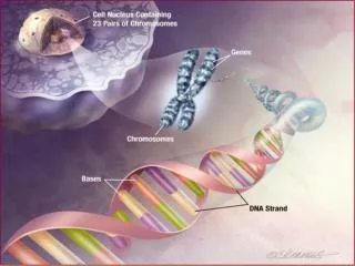
Study Objective • Primary objective is to examine the effects of aligned fractures (or cracks) on seismic wave amplitude • Fractures are difficult to mathematically describe and numerical modeling for fractures is at its infancy • The physics of wave propagation in media containing micro cracks and fractures is also not well known • Physical Modeling can provide an insight into wave mechanism in fractures and micro cracks without necessarily understanding its physics • Eventually seismic response due to faults and micro cracks could be extracted from physical modeling data and it could be used to produce better numerical models.
General Overview • A total of 8 glass models with differing fracture orientation have been supplied to date. • This include a blank glass for the purpose of calibration and inverse filter development. • More than 40 different seismic surveys (transmission and reflection) have been conducted on these blocks • A lot of seismic surveys were precursor to other more detailed surveys. • Some glass models were improvements on previously faulty designs • Most seismic surveys (especially transmission surveys) were optimized for immediate or quick seismic wave amplitude response • Detailed analysis and advanced seismic data processing techniques are only now beginning to be applied to the data
AGL’s physical modeling setup AGL’s 3m X 2m X 1.5m marine acquisition system (tank) 300 KHz Spherical Transducer
Typical Experiment Setup and Instrumentation • Acquisition Type Common Offset Single Source Transmission/Reflection • Minimum/Constant Offset 2cm • Number of Lines/ Data Set 60 • Number of Source Positions/Data Set 100 • Receiver/Shot Interval 0.25cm • Vertical Stack Fold 20 • Total Number of Traces 40,000 • Source Type 300 KHz Spherical Transducer • Receiver Type 300 KHz Spherical Transducer • Energy Level 1 • Sample Interval 2ms • Total Trace Length 4000ms • Preamp Gain (db) 40 • Scale Factor 1:10000
Blocks C3 and C4 Block C3 (Plain Block) Block C3 (Plain Block) Block C4 (Fractured Block) Block C4 (Fractured Block)
Blocks C3 and C4 High Amplitude Clip Time Slice 68ms First Arrival at 42ms Fracture Zone Lower Amplitude Clip
Future Work and Conclusion • Inverse Filter Design Minimum Offset = 2cm Minimum Offset = 3cm Minimum Offset = 4cm Differing Offset Reflection Survey conducted on Block C4
Inverse Filter Design 150 ms seismic trace extracted from Block C3 (Plain Glass) Simple Band Pass Filter Design to be applied on Glass Model data (8,16,48,60)
Future Work and Conclusion Minimum Offset = 2cm Minimum Offset = 3cm Minimum Offset = 4cm Resulting Seismic Section after Decon and Band Pass Filtering
Preliminary Results and Discussion • Study shows encouraging preliminary result for using laser etched crystals to model fracture swarms • Seismic wave amplitudes in from both transmission and reflection measurements seem to increase on entering the fracture zone