Download
1 / 42
420 likes | 576 Views
Challenges and Trends in Beam Diagnostics. Prof. Carsten P. Welsch. First: What is oPAC ?. O ptimization of P article Ac celerators 22 ESRs >30 Partner Institutions 6 M€ www.opac-project.eu. Overview of Consortium. Beneficiary partners Associated partners. Adjunct Partners.

E N D
Challenges and Trends in Beam Diagnostics Prof. Carsten P. Welsch
First: What is oPAC ? • Optimization of Particle Accelerators • 22 ESRs • >30 Partner Institutions • 6 M€ www.opac-project.eu
Overview of Consortium • Beneficiary partners • Associated partners
Adjunct Partners • Part of the long term strategy – oPAC is growing
Why needed ? • Well suited as cross-sector collaboration is key to our research. • Essentially all large-scale experiments require international cooperation • Research area needs significantly more trained accelerator experts; • Few universities in EU provide structured courses – oPAC drives innovation in researcher training
WP2 – Beam physics • Development of designs for possible LHC upgrade options • Advanced beam physics problems at light sources • Optics and lattice design studies for the interaction region design of the LHC experimental insertions • LHeC as a future upgrade option of the LHC • Simulation studies into halo generation in high brightness hadron beams • Studies into beam loss patterns at ESS • Design and development of resonant structures as Schottky noise detectors for various frequencies • Optimization of the layout of the LHC collimation system • Improvement of the understanding of non-linear beam dynamics effects in light sources
WP3 – Beam Diagnostics • Beam halo monitor development • Optimization of beam instrumentation for light sources • Cryogenic SQUID-based beam current monitor • Beam Loss Monitors for use in Cryogenic Environments • Methods for measuring the beam profile in high intensity beams • Laser-wire beam profile monitor for measuring the transverse beam profile of an H- beam • Optimization of 10Be detection • Design a detection system for verifying a 3D method of image reconstruction for Intensity Modulated Radiotherapy Treatment (IMRT)
WP4 – Simulation Tools • Included in most R&D project, plus: • Development of a simulation suite based on the multilevel fast multipole method • Development of a GPU-based PIC solver
WP5 – Control Systems • Links all R&D projects, plus: • Adaptation of existing open-source control systems from compact accelerators to large scale facilities • Improvement of the process to identify the needs for accelerator instrumentation
Motivation: Ideal Training. WP6 - Training • Objective: Train the next generation of accelerator experts in best possible way • Provide them with ideal skills basis for their future careers • Promote collaboration and cross sector exchange • Secondments to under how R&D works at different places
Training – each Network Node • Provide trainees with broad skills base • 100% focus on research project • In accordance with national (PhD) regulations • Enable secondments between nodes • Promote knowledge exchange and collaboration across the network • Initial plan fixed in CDPs, additional opportunities already taken (e.g. JUAS, IPAC, etc.)
Network-wide Training • Schools in Accelerator Physics (CAS, JUAS) and Complementary Skills • Topical Workshops on focused research areas • Training Days on expert topics • Conference and Symposium to summarize and disseminate research results internationally • Provision of seminars, contributions to conferences, etc. • Secondments between partners
Diagnostics Challenges • Advanced beam diagnostics methods (examples) • Non-invasive beam profile monitoring • Absolute measurement of nA beams • Beam loss monitors and detector technology • Limitations and open questions
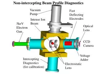
IPM • Souce: J. Egberts, CEA • Based on ionization of rest gas • Challenges • Required residual gas pressure • 1D beam profile ‚only‘ Peter‘s and Charlotte‘s talk
BIF Monitor • Measures light from rest gas, excited by beam • Challenges: • Very low cross sections • Isotropic light emission • Rest gas pressure requirements Peter‘s and Charlotte‘s talk F. Becker, GSI
Atom Gas Jet • Proof-of-principle setup at the CI; • Gas jet and IPM; • Designed for use with low energy antiproton beams: • Profile Monitor • Collision experiments. • V. Tzoganis, A. Jeff M. Putignano, et al., Nucl. Instr. Meth. A (2012). V. Tzoganis, APL (2014), accepted.
Electron Beam Scanner Derive beam profile from deflection of low energy electron beam scanned across the high energy proton beam Courtesy of W. Blokland and R. Jones
Electron Beam Scanner Look at the deflected projection of a tilted sheet of electrons Quadrupoles Deflector dy dx Multiple scans Electrons take the derivative to get the profile Courtesy of W. Blokland and R. Jones.
Challenges Courtesy of W. Blokland and R. Jones
Accelerator physicists Instrumentation specialists Low density / difficult to measure Definition: What is 'Halo' ? General definition difficult to make:
Problem • Very high intensity in core: • Saturates pixels • Signal overflow to neighbouring pixels • Tail regions are being modified, falsified measurement. • Solution: Concentrate measurement on tail region ONLY as this is the interesting part ! • How ??
(1) Aquire profile (2) Define core (4) Re-Measure (3) Generate mask Halo Monitoring: Core Masking C.P. Welsch et al., Proc. SPIE (2007) J. Egberts, et al., JINST 5 P04010 (2010)
Measurements at UMER • 10 keV e- beam, Phosphor screen • iCCD camera • Verification of earlier lab measurements • Reconstruction of beam profile with DR of 105 • Effects from diffraction on DMA are minimal !! H. Zhang, et al., Phys. Rev. STAB 15, 072803 (2012)
Advantages • Can be used with any raditiation (OTR, ODR, SR, Smith-Purcell, Cherenkov, etc.); • Suitable for any charged particle beam; • Advanced measurements possible: XDR, emittance, phase space mapping, injection optimization, etc. • More to come... See Blaine‘ s talk
Additional challenges • Approaching the resolution limit, e.g. sub 100 nm beam size measurements using OTR (Pavel and Konstantin); • FELs and Light Sources (Volker and Laura); • Laser wire scanners (Thomas).
Absolute Current Measurement • Highly desirable ! • Callibration of other monitors, • Direct link to experimental output. • Challenges: • Signal levels VERY low, • Signal/noise critical, • Isolation against vibrations, rf noise • ...many more...
Cryogenic Current Comparator The CCC consists of: • SC pickup coil, • High efficient SC shield, • High performance SQUID measurement system. Harvey, Rev. Sci. Instrum. 43 (1972) DITANET: Febin
SQUID Superconducting QUantumInterference Device • Most sensitive magnetic flux detector, The working principle makes use of: • Superconductivity, • Flux quantization in SC rings, • Josephson effect. A SQUID consists of a SC ring with one or two weak links (Josephson tunnel junctions).
Measurement Principle • Couple to azimuthal magnetic field, • Screening current induced in SC coil with ferromagnetic core, • DC SQUID for sensitive detection of coil magnetic field, • Strong shielding against magnetic noise is key ! (14 ring cavities give 200 db shielding factor) M. Schwickert
Prototype @ GSI • GSI prototype (A. Peters, 1997) Resolution: 250 pA/√Hz → 8 nA (1 kHz readout) → 2×10⁹ U28+/s
ELENA CCC Challenge: accurately measure low-intensity beams Proposal: measure induced magnetic field with a SQUID Crucial: tiny level of signal magnetic field requires advanced shielding strategy Courtesy of Miguel
Beam Loss – 5 MW beams • Power density, in Gy/sec, for 1 W/m distributed beam loss on a beam pipe, at 200 MeV and 2 GeV. • Additional Monte Carlo Studies required, different loss scenarios under consideration – lot of expertise at CI • Source: M. Jarosz, ESS – Proc. IBIC (2013)
Diamond Detectors • Fast & sensitive • Used in LHC to distinguish bunch by bunch losses • Investigations now ongoing to see if they can work in cryogenic conditions See Pavel and Erich‘s talks Courtesy of E. Griesmayer
Cryogenic Monitors • Silicon • Successfully used at 1 K at CERN in 1976 • Diamond • Successfully in use as LHC BLM at room temperature • Better resistance to radiation than Si at room temperature • Less leakage current than Si at room temperature • Does it work in liquid helium? • Liquid helium ionisation chamber • Advantage : no radiation hardness issue • Disadvantage : slow (charge mobility of 0.02 cm2/V/s) Courtesy of R. Jones – see Marcin’s talk
Upcoming Events • School on Accelerator Optimization (July 2014) • School on Laser Applications (September 2014) • Topical Workshop Beam Diagnostics (March 2015) • Conference on Laser Applications (March 2015) • Outreach Symposium, Liverpool (June 2015) • Conference on Accelerator Optimization (October 2015)
Stay tuned !! • URL: (http://www.)opac-project.eu
Summary • Beam Diagnostics are an exciting topic for research and ideal for training; • Current performance limits shall be discussed at this workshop – talks to stimulate discussion; • There are still very significant challenges that will require close international collaboration. Thanks for your attention !!