Download
1 / 95
990 likes | 1.28k Views
Chapter 3: Filtering & Enhancing Images. This chapter is about image processing , since the methods take an input image and create another image as output. Other appropriate terms often used are filtering, enhancement , or conditioning .

E N D
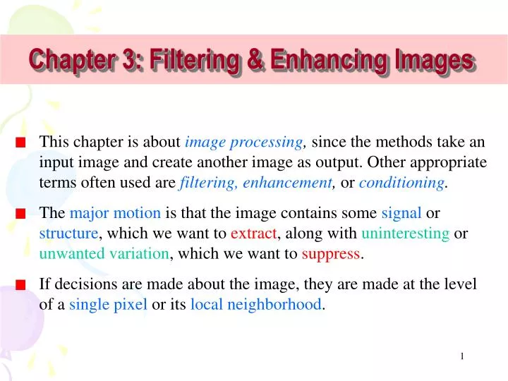
Chapter 3: Filtering & Enhancing Images • This chapter is about image processing, since the methods take an input image and create another image as output. Other appropriate terms often used are filtering, enhancement, or conditioning. • The major motion is that the image contains some signal or structure, which we want to extract, along with uninteresting or unwanted variation, which we want to suppress. • If decisions are made about the image, they are made at the level of a single pixel or its local neighborhood.
Contents • (1) What Needs Enhancement? • (2) Image Enhancement by Point Operation • Contrast Stretching • Digital Negative • Intensity Level Slicing • Histogram Modeling • (3) Image Enhancement by Spatial (mask) Operation • Noise Smoothing • Median Filtering • Sharping Masking • Zooming
Scratches What Needs Enhancement? • Before launching into the methods of this chapter, it is useful to review some of the problems that need them. Two general categories of problems follow. • An image needs improvement • Low‑level features must be detected Example 1: Scratches from original photo of San Juan are removed
Example 2: Intensity of photo of Alaskan Pipeline rescaled to show much better detail Example 3: Image of airplane part has edges enhanced to support automatic recognition and measurement
This chapter deals mostly with traditional methods of image enhancement. Before moving on, it is important to define and distinguish the terms. • Image enhancementoperators improve the detectability of important image details or objects by man or machine. • Example operations include noise reduction (smoothing), contrast stretching, and sharpening (edge enhancement).
Image Enhancement • Sharpening of image features ( such as edges or boundaries) to make a graphic display more useful for analysis. • Do not increase information content but increase dynamic range of chosen feature to be detected more easily.
Example Left- Original sensed fingerprint; Center- Image enhanced by detection and thinning of ridges; Right- Identification of special features called minutia, which can be used for matching to millions of fingerprint representations in a database.
Image Enhancement - Operations (1) Point operations • Contrast stretching • Noise clipping • Window slicing • Histogram modeling
Image Enhancement -Operations • (2) Spatial (mask) operation • Noise smoothing • Median filtering • Sharping masking • Zooming
f(x) gin gout=f(gin) Output image Input image Mapping function Points Operation • Two ways to enhance images: • Changing the intensity values of pixels • Transforming the pixels via a single function that maps an input gray value into a new output value Remapping the gray values is often calledstretching伸缩
Definition - A point operatorapplied to an image is an operator in which the output pixel is determinedonlyby the input pixel, • Out[x, y] = f (In[x, y]); • possibly function fdepends upon some global parameters. • A contrast stretching 对比度伸缩 operator is apoint operator that uses a piecewise smooth function f (In[x, y]) of the input gray level to enhance important details of the image.
Contrast Stretching • Improve contrast due to poor /nonuniform lighting conditions or nonlinearity or small dynamic range of image sensor. • Typical contrast stretching transformation:
Contrast Stretching Where u is the gray-level values of input image 0-255, v is the transformed gray-level values of output image 0-255, L=255
Mapping function Input image 255 gout f(x) 0 255 gin Output image Output image
Contrast Stretching (a) Original (b) Enhanced
Contrast Stretching (a) Original (b) Enhanced
Contrast Stretching • Example: (a) Original (b) Enhanced
Contrast Stretching • Clipping: when • Useful for noise reduction when input signal is known to lie in the range [a,b]. • Thresholding: when a=b=t (threshold) • Output becomes binary. • Useful for binary or other images that have bimodal distance of gray levels. • Can define other similar operations.
Contrast Stretching Cliping and thresholding
Contrast Stretching Cliping and thresholding
Digital Negative • Create digital negative of images • Display of medical images
Mapping function (Reverse) 255 gout f(x)=x -1 0 255 gin Input image Output image
Digital Negative Digital negatives
Digital Negative Digital negatives
Digital Negative Digital negatives
Intensity Level Slicing Without background: With background:
Intensity Level Slicing Fully illuminates pixels lying in the interval [a,b] and removes the background. • Segmentation of certain gray level region • e.g. Image from remote sensing.
Intensity Level Slicing (a) Visual and infrared images (b) Segment images Level slicing of intensity window[175,250]
gout gout gout gout gout gout gin gin gin gin gin gin Various Mapping Functions
Number of pixels Number of pixels Fig.a - bad image Fig.b - good image Gray level r Gray level s Histogram Modification When is it necessary to modify the Histogram of an image • The histogram of the “bad” image is very narrow (Fig. a), while the histogram of the “good” image is more spread (Fig. b). • To change a “bad” imageto the “good” image, we need modify the histogram.
H(z) Dark image Dark image Gray level z Histogram Modification • The histograms of fourbasic types of images : • The gray levels are concentrated toward the dark end of the grayscale range. Thus this histogram corresponds to an image with overall dark characteristics.
H(z) Bright image Gray level z Bright image Histogram Modification • Just is the opposite of the above.
H(z) Low-contrast image Gray level z High-contrast image H(z) Low-contrast image High-contrast image Gray level z • The histogram has a narrow shape, which indicates little dynamic range and thus corresponds to an image having low contrast. • The histogram has significant spread, corresponding to an image withhigh contrast.
s=T(r) How can we modify the Histogram • Suppose that the grey levels in the original image are given by the values, which are obtained from a variabler. • The grey levels in the new image are given by the values , which are obtained from a variables. • We would like to find a transformation s = T (r) such that the probability densityfunctionpr(r) in original image(Fig. a)is transformed into a probability density function ps(s) in the new image,which looks like that in Fig. b. pr(r) ps(s) Gray level r Gray level s
Number of pixels Number of pixels T Gray level s Gray level r r r+dr s+ds s [r, r+dr] [s, s+ds] • Since pr(r)isthe probability density function of random variable r. • The number of pixels with grey level values in the range r to r +drisPr(r)dr. • The transformation we seek will transform this range to [s, s+ds]: [r, r+dr][s, s+ds]
The total number of pixels in this range will remain the same but in the enhanced image this number will be ps(s)ds:ps(s)ds = pr(r)dr • This equation can be used to define the transformation T that must be applied to variable r to obtain variable s, provided we define function ps(s).
Histogram Equalization • Histogram equalization is an important method in histogram modification. • Histogram equalizationis often tried to enhance an image. • The two requirements on the operator are that • (a) the output image should use all available gray levels • This requirement means that the target output image uses all gray values z = z1, z = z2, … z = zn • (b) the output image has approximately the same number of pixels of each gray level.
Ps(s) is uniform, i.e. a flat histogram to obtain an image with a more balanced contrast • i.e. the transformation required is just the cumulative distribution function (c.d.f.) of u
Discrete case i.e. use the histogram in place of the p.d.f. in the continuous case (the discrete equivalent to the p.d.f.) • similarly, the continuous c.d.f. is now replaced by ⇒ a monotonically increasing sequence
if the original digital image has L gray levels, it may be necessary to re-quantize skto the same set of L discrete levels also Method1: Method 2:
method 1 is more efficient but it pre-supposes that uniform quantization is appropriate Example 1 (for 3 bit image)
Note: (1) re-quantization method is arbitrary (2) may not get a 1-1 mapping ⇒ inverse problem (3) may not get a flat histogram unless L is large
Original image Original histogram Histogram after equalization Modified image Example of Histogram Equalization
Original histogram Original image Modified image Histogram after equalization
Histogram Equalization (a) Input image (b) Processed image
Histogram Equalization (d) Processed image (c) Input image
Histogram Equalization (e) Input image (f) Processed image
Spatial (mask) Operations • Operations performed on local neighborhood of input pixels. • Usually image is convolved with a finite impulse response (FIR) filter-spatial mask.
Mask operation: 1. Centre the mask at (x, y). 2. Multiply every pixel that is contained within the mask area by the corresponding mask coefficient. 3. Add the products together. 4. Either replace f (x, y) by the sum or compare the sum with a threshold and replace f (x, y) according to the comparison. 5. Repeat 1 to 4 for the whole image.