Download
1 / 8
80 likes | 209 Views
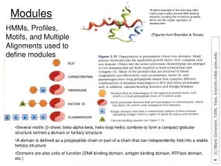
Modules assembly plan. 19/09/2013. Detector layout. Layout -TDR-5 Baseline for TDR. Inner Barrel (IB) The Inner Barrel consists of the three innermost layers: Inner Layers layer 0, layer 1 and layer 2. Stave. Flexible Printed Circuit (FPC) or Flex. Inner Barrel (IB): 3 layers pixels

E N D
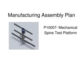
Modules assembly plan 19/09/2013
Layout -TDR-5 Baseline for TDR Inner Barrel (IB) The Inner Barrel consists of the three innermost layers: Inner Layers layer 0, layer 1 and layer 2. Stave Flexible Printed Circuit (FPC) or Flex. Inner Barrel (IB): 3 layers pixels Radial position (mm): 23.4, 31.5, 39.3 Length in z (mm): 270 Nr. of staves: 12, 16, 20 Nr. of chip/stave: 1x9 Nr. of chip: 108, 144, 180 Pixel Chip Coldplate Spaceframe
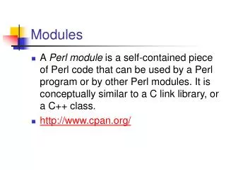
Layout -TDR-5 Baseline for TDR Stave Spaceframe ColdPlate ColdPlate Outer Barrel (OB): 4 layers pixels Radial position (mm): 194, 247, 353, 405 Length in z (mm): 843, 1475 Nr. of staves: 22, 28, 40, 46 Nr. of modules: 176, 224, 560, 644 Nr. of chip: 2464, 3136, 7840, 9016 Nr. of chip/module: 2x7 Nr. of modules /half stave: 4, 4, 7, 7 Nr. of modules/stave: 8, 8, 14, 14 Nr. of chips/stave: 112, 112, 196, 196 Half-Stave Module Pixel chip (15mmx30mmx0,05mm)
Quantity of modules and solderings • Inner barrel • 48 modules x 2 + 10% ~ 110 staves • 990 chips, 49500 solderings • Outer barrel • 1602 modules +10% ~ 1800 modules • 25200 chips, 1260000 solderings Total time for production ~ 2 y
Goals of automatic system • achieve placement of chips and position (x,y,z) with 5-10 mm accuracy • produce ~ 1 module/day with 100% working contacts
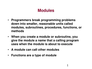
Module assembly procedure by laser soldering • Placement of chips on vacuum table and position check • Placement of flex on support and alignment with macor grid (included in support) • Placement of flex on chip and alignment • SnAg balls deposition and check • Soldering of one chip • Repeat steps 5 and 6 for all chips • Soldering check • Final check of chips position
Module assembly procedure by laser soldering Additional info: • Fluxless laser soldering might need further tool and/or steps in the procedure as we are studying: • Heating of chips (T~ 50-100 C) • Plasma treatment of chips and flex just before soldering • Soldering under N2/H2 (95/5) atmosphere