Download

1 / 79
810 likes | 1.1k Views
Timing Analysis in Quartus. Features. Quartus is capable of doing single clock design timing analysis and multi-clock design timing analysis Single clock timing analysis Fmax (maximum clocking frequency) Tsu, Th, Tco (setup time, hold time, clock-to-out time)

E N D
Features • Quartus is capable of doing single clock design timing analysis and multi-clock design timing analysis • Single clock timing analysis • Fmax (maximum clocking frequency) • Tsu, Th, Tco (setup time, hold time, clock-to-out time) • Slack analysis for Fmax (incl. delays to/from pins) • Multi-clock analysis • Allows user to analyze timing for a design containing register-to-register paths which are controlled by different clocks • Slack analysis is used • Combinatorial Loop Detection • Quartus automatically detects combinatorial loops
Features • Different types of timing information (Refer to the compilation section for more information) • Timing without place & route • Timing with place & route • A mix of both for a hierarchical design • By default, timing analysis is performed automatically after compilation • Can be disabled • Timing information can be exported to other EDA tools via VHDL, Verilog and Standard Delay File (SDF)
In This Section • Timing analysis for a single clock system • Register Performance • Setup Time • Hold Time • Clock-to-Out • Making Timing Assignments • Timing analysis of a multi-clock system • How to make multi-cycle assignments • Timing Wizard
Compile Design Step 1: The internal fmax is 83.19 Mhz. This value is automatically given for each clock in the Message Window (Processing Tab) Step 2: Investigate the type of delay in this design
Reporting Timing Results • Timing information is part of the Compilation Report • Summary Timing Analyses • fmax (not incl. delays to/from pins) or fmax (incl. delays to/from pins) • Register-to-Register Table • tsu (Input Setup Times) • th (Input Hold Times) • tco (Clock to Out Delays) • tpd (Pin to Pin Delays) • All timing results are reported here
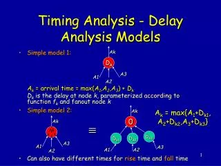
fmax (not incl. delays to/from pins) tco B tsu C E Clock Period Clock Period = Clock-to-out + Data Delay + Setup Time - Clock Skew = tco + B + tsu - (E - C) Fmax = 1/Clock Period
fmax Analysis fmax values are listed in ascending order. The worst fmax is listed on the top. Quartus Detected Clock Select fmax Destination Register Worst fmax
fmax Analysis • Timing Analysis By Default Lists 10 Worst Paths • Can Change in Project -> Timing Settings (discussed later) Source registers and associated fmax values Expand to see the source registers feeding the selected destination register
fmax Analysis • To Analyze the Path More Closely Highlight & right mouse and select List Paths The steps above are similar for all timing path analysis in Quartus
fmax Analysis Data Delay (B) Destination Register Clock Delay (E) Source Register Clock Delay (C) Clock to Output (tco) Setup Time (tsu) Messages Window (System Tab) in Quartus B tco tsu C E 1 = 83.08 MHz 0.33 ns + 11.257 ns + 0.45 ns + 0.00 Clock Period
fmax Analysis This signal path consists of 11 locations Destination Cell Interconnect Delay Cell Delay Running Total The convention above is similar for all timing path analysis in Quartus
Carry Chain in Data Delay Path Floorplan: Logic Cell View Note: If the delay path involves a carry chain, you can only see the delay path value in the Floorplan when the Floorplan is set to Logic Cell View. LAB View does not show that delay path. 0.191ns is equal to the carry chain delay plus combinatorial delay 0.000 ns + 0.191 ns = 0.191 ns 0.000 ns is the carry chain delay (interconnect delay) 0.191 ns is the combinatorial delay
Locate Delay Path in Floorplan Highlight path Right click & select Locate The steps above are similar for all timing path analysis in Quartus
Locate Delay Path in Floorplan 11.257 ns is the total register to register delay path
Fmax (incl. delays to/from pins) A B tco tsu Q C External Input Delay External Output Delay E Input Pin Period Clock Period Out Pin Period System Fmax = 1 / (the longest of the 3 following delays: Clock Period, Input Pin Period, Output Pin Period) Clock Period = C + tco + B - E + tsu Input Pin Period = External Input Delay + A - C + tsu Output Pin Period= E + tco + Q + External Output Delay
Input Pin Period A tsu C External Input Delay Input Pin Period Input Pin Period = External Input Delay + A - C + tsu Value entered in Quartus (shown later)
External Input Delay External Input Delay Altera Device Imaginary Register ET A tco tsu EC C External Input Delayis used to model the delay between an imaginary register and a register inside an Altera device External Input Delay= EC + tco + ET Input Pin Period = External Input Delay + A - C + tsu
Output Pin Period tco Q External Output Delay E Output Pin Period Output Pin Period = E + tco + Q + External Output Delay Value entered in Quartus (shown later)
External Output Delay Altera Device External Output Delay Imaginary Register Q ET dst tco tsu E EC External Output Delayis used to model the delay between a registered output from an Altera device to an imaginary register External Output Delay= ET + tsu - EC Output Pin Period = E + tco + Q + External Output Delay
Fmax (incl. delays to/from pins) The worst fmax is shown at the top by default. Select fmax (incl. Delays to/from pins) Fmax values External Delay is shown in Messages Window after List Path
Setting External Input/Output Delay • Default (Global) External Delay for all I/Os 1)Project -> Timing Settings 2)Select Default External Delays 3)Set Delay Value(s)
Setting External Input/Output Delay • Individual Pin(s) 1)Tools -> Assignment Organizer 2)Locate Pin(s) 3)Select Timing from Assignment Categories 3)Set Delay Value(s) for Pin(s)
Setup Time Analysis Data delay intrinsic tsu tsu Clock delay tsu = data delay - clock delay + intrinsic tsu
Setup Time Analysis The greatest setup time is shown at the top by default. Input Pin Name Clock Name Select tsu All Registers Fed by Pin
thold Analysis Data delay intrinsic thold thold Clock delay thold = clock delay - data delay + intrinsic thold
thold Analysis The longest hold time is shown at the top by default. Input Pin (Data) Name Register Name Select th Clock Name Negative hold times are shown as “<= 0”
tco Analysis intrinsic tco Data delay tco Clock delay clock delay + intrinsic tco + data delay = tco
tco Analysis The slowest clock-to-output time is shown at the top by default. Output Pin Name Clock Name Select tco Register Name
Timing Analysis Options • Used to Limit Which Paths Are Displayed by Timing Analyzer • Two Ways to Set Options • Project -> Timing Settings -> Other Requirements & Options • Project -> Timing Wizard • Examples • Cut Off Feedback From I/O Pins (next slide) • Cut Off Clear and Preset Signal Paths • If checked, Quartus Will Not Analyze Register Clear and Preset Delays • Cut Off Read During Write Signal Paths • Turn ON if Read During Write is an Invalid Path
Option: Cut Off Feedback from I/O Pin Global Timing Option: Cut off feedback from I/O Pin • Used to break I/O pin from the analysis • When on, paths A and B are valid. C is not valid. • When off, paths A, B, and C are valid. I/O Pin Register 2 Register 1 B A Q D C clk
Timing Analysis Options • Used to Limit How Many Paths Are Displayed by Timing Analyzer • How to Set Option • Project -> Timing Settings -> Timing Analysis Reporting • Examples • Show “XX” Source Nodes Per Destination Node • Controls by Number How Many Paths Are Displayed • Exclude Paths With fmax Greater Than “XX” • Controls by Parameter Value (fmax) How Many Paths Are Displayed • Exclude Paths For tsu, tco, thd Also
Timing Analysis Options List 10 Paths List Paths with fmax less than 50 MHz List Paths with tsu greater than 3 ns
Single Clock Timing Analysis • The timing analysis that we just went over can be classified as a single clock frequency analysis • Single clock frequency analysis is automatically done during each compile • Quartus will automatically detect clocks if no assignments are made • More information about clock assignments is coming up in multi-clock timing analysis • Check results in Report Window
Timing Assignments • Timing assignments have two impacts on designs • 1. During timing analysis, they specify required times the design is measured against • 2. During compilation, they become timing requirements which Quartus has to meet when performing timing driven compilation (TDC) • Note: by default, TDC is on • 5 types of timing assignments exist: • fmax, tsu, thold, tco, tpd • These timing assignments can be assigned globally or locally
Examples of Timing Assignments Timing Assignments used in Timing Analysis fmax timing assignment The values are BLACK, because Actual fmax meets the Required fmax tsu timing assignment. The numbers are RED, because the Actual tsu does not meet the Required tsu
Timing Driven Compilation • Timing Driven Compilation (TDC) directs the compiler to synthesize and place logic to meet timing specified requirements • Critical paths will be placed closer together in the device Optimize for I/O Timing and/or Internal Timing Choose Normal or Extra Effort (works harder & takes longer)
Global Assignment: Timing Settings Global Clock Assignment for a single clock design For a design with separate clocks, you can enter the required fmax. The Default required fmax will be applied to each individual clock in the design.
Global Assignments - Timing Settings Global tsu. All input or bidirectional pins are measured against this tsu requirement Global th. All input or bidirectional pins are measured against this th requirement Global tco. All registers driving outputs or bidirectional pins are measured against this tco requirement Global tpd. All pin-to-pin delays are measured against this tpd requirement
Individual Assignments • tsu (setup time) and th (hold time) assignments • Single point assignment • Point-to-point assignment • tco (clock-to-out) assignment • Single point assignment • Point-to-point assignment
Timing Assignments • What can be tagged with a timing assignments? • Registers (all) • Clock Pins (all) • Input Pins (tsu, th) • Output Pins (tco) • Bidirectional Pins (all)
Setup/Hold Requirements • Assignments can be either single point or point-to-point • Single point setup/hold requirements • States that the setup/hold time is required on every register that the pin feeds Assign single point setup/hold requirement to the data pin
Setup/Hold Requirement: Point-to-Point • The setup/hold time is required only for the specified path Assign point-to-point setup requirement to the input pin and the destination register Reg1 data0 Reg2
Clock To Out Requirements ... ... • Either a single point or a point-to-point assignment • Same idea as setup/hold time requirements • Tco requirement on a clock pin • Means that all Tco paths that start from the specified clock must meet this requirement
Clock To Out Requirements • tco requirement on an output pin • Means that all paths from clocks to the specified output pin must meet this requirement
Clock To Out Requirements • Point-to-point tco requirement • Can specify that all paths that go from a specific clock pin to a specific output pin must meet this requirement
Example: Assign Setup Requirement Step 1: Enter the data pin name or use the Node Finder to locate data pin name and/or register name Menu Bar: Tools > Assignment Organizer... Step 2: Select Timing from the Assignment Category box Step 3: Choose tsu Requirement from the drop-down list in the Settings section
Example: Assign Setup Requirement Step 6: Click Add to add the assignment Step 4: Type in the setup requirement Step 5: Use Fed by: to create a point-to-point requirement
Multi-Clock Frequency Analysis • Allows user to analyze timing for a design containing register-to-register paths which are controlled by different clocks • Unless Specified, Quartus Treats Individual Clocks As Having the Same Frequency and Phase Combinatorial logic Register 2 Register 1 data tsu tco clk2 clk1 launching edge clk1 clk2 capturing edge