Download
1 / 35
400 likes | 988 Views
Carbon Dioxide Systems. Carbon dioxide properties Storage Uses Limitations Types of systems Local Application Total Flood. 1. Carbon Dioxide Properties. [.03%] in atmosphere Colourless, odourless Density 1.5 times air Non-conductive Forms dry ice snow Displaces oxygen and cools.

E N D
Carbon Dioxide Systems • Carbon dioxide properties • Storage • Uses • Limitations • Types of systems • Local Application • Total Flood
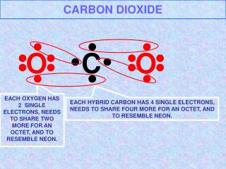
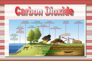
1. Carbon Dioxide Properties • [.03%] in atmosphere • Colourless, odourless • Density 1.5 times air • Non-conductive • Forms dry ice snow • Displaces oxygen and cools
Phase Diagram • Fig. 7-1, page 115 • Solid phase • Vapour phase • Liquid phase • Triple point • Critical temperature
2. Storage • High Pressure Cylinders • Low pressure Storage Containers
High Pressure Cylinders • Liquid CO2 • @ 700 F,850 psi, • Can range 32 0F – 120 0F • Capacity, 5- 100 lb • Relief valve, 2500-3,000 psi • Usually matching reserve • Fill density 68% • Dip tube
Low Pressure Storage Containers • Constant O 0F, 300 psi • Refrigerated, pressurized • Electrical supervision • Capacity in tons • Insulated • Pressure relief • multiple discharges possible
3. Uses • Ordinary combustibles, class A • Flammable liquids, class B • Electrical hazards, class C • See examples in text
4. Limitations Not with • Oxidizers • Reactive metals • Metal hydrides • Occupied areas
Personnel Hazards • Ideally unoccupied • [CO2] > 34% • [O2] < 15% • Continuous pre-discharge alarms • Breathing apparatus • Voice alarm systems • Exits
Personnel Hazards continued • Signs • Training • Time delay • Manual activation • Manual override • Scented gas
5. Types of Systems • Total flooding • Local application • Hand hose lines • Standpipe systems and mobile supply
6. Local Application • Rate-by-volume local application • Rate-by-area local application
Rate-by-volume local application • Imaginary volume • object flush on solid floor • add 2 feet to each open surface Vimg = (L + 4 ft) x ( W + 4 ft) x (H + 2 ft) R = Vimg x ( 1lb/min/ft3) W = R x D
Rate-by-area local application • Pages 127-131 • 2D horizontal fires • flammable liquids • diptanks, drainboards • min. discharge 30 sec. • If storage is high pressure, add 40%
Nozzles • Square coverage • typically 20-30 ft2 • specifications from manufacturer
Steps 1. determine max. width 2. Extend line horizontally to intersect nozzle graph different scales for drainboard and diptank 3. Drop vertical line from point of intersection 4. Extend horizontal line from point of intersection 5. Read flow rate Fliquid (lb/min)
6. Number of nozzles for diptank Nliquid 7. FRliquid =Nliquid xFliquid 8. Number of nozzles for drainboard Ncoated 9. FRcoated =Ncoated xFcoated 10.FRtotal = Frliquid + Frcoated 11. W (lb) = FR (lb/min) x D (min) 12. If storage is HP, increase FR by 1.4
7. Total Flood • Multi-step procedure • Evaluate room • Evaluate fire • calculation
Evaluate enclosure integrity • Acoustical ceiling tiles • door closers • Windows • Other openings • Floor openings • Wall joints
Evaluate Enclosure Integrity continued • Wall rigidity • HVAC • Supply shut-off • Exhaust dampers • Fan test
Evaluate Personnel Hazards • Record activity • Time to exit • Worse case time to exit • Door recognition test • Warning sign effectiveness • Review personnel hazards • Don’t increase hazard
Evaluate fire scenario • Control ignition sources • See list pages 133-4 • Surface or deep-seated fire?
Measure room volume • L x W x H • Can reduce for solid objects • Add plenum space
Determine type of combustible • Material • Surface or deep-seated fire
Determine Minimum design concentration • See fig. 7-10 • Theoretical minimum • Minimum design concentration • 34-75%
Determine volume factor • See 7-ll and 7-12 • Lb CO2/ ft 3 • For design conc. = 34% • Varies with room size • Minimum values exist
Determine basic quantity of CO2 • Assumes design conc. = 34 % • Qbasic (lb) = V(ft3) x volume factor (lb/ft3)
Determine material conversion factor • See 7-13 • Dimensionless number • Increases quantity • Materials with design conc. > 34%
Adjust quantity for temperature • 1% increase / 5F0 > 2000F • 1% increase / 1F0 < 00F
Adjust quantity for unclosable openings • Add extra gas • See 7-14 • Need area of opening • Distance center below ceiling
Other scenarios for loss of gas • Supply air • Calculate quantity • Apply flooding factor • Apply material conversion factor • Apply temperature compensation
Consider extended application • For other leaks • Deep-seated fires • Maintain design conc.
Calculate pressure relief venting • Very tight rooms • X = Qtotal / 1.3 P ½ • See 7-15 • unlikely
Determine number of nozzles • One / 400 ft2 ceiling area • Max 20 ft spacing • Max. 10 ft from wall
Calculation form • See page 145