Download
1 / 29
300 likes | 411 Views
Dual Recycling in GEO 600. H. Grote, A. Freise, M. Malec for the GEO600 team Institut für Atom- und Molekülphysik University of Hannover Max-Planck-Institut für Gravitationsphysik 9. July 2003. Dual Recycling Concept.

E N D
Dual Recycling in GEO 600 H. Grote, A. Freise, M. Malec for the GEO600 team Institut für Atom- und Molekülphysik University of Hannover Max-Planck-Institut für Gravitationsphysik 9. July 2003
Dual Recycling Concept • two recycling cavities enhance independently the carrier light and the signal sidebands • shot noise limited sensitivity is improved (typically by a factor of 102 to 103) MPR MSR
Adjustable Sensitivity TMSR = 0,1% TMSR = 1% TMSR = 5% Strain sensitivity [1/sqrt(Hz)] Therm. noise Frequency [Hz]
Dual Recycling Configuration PR cavity control (25kHz) SR cavity control (400/40 Hz) Michelson control (300Hz)
PR Error Signal Michelson Tuning [Degree] PR Tuning [Degree]
Problem: Lock Acquisition • PR has to be locked first, but state space is limited • Lock Michelson in largely detuned SR state (larger state space) • MI optical gain depends on SR tuning Michelson error signal Optical gain [Arb.] Signal Recycling error signal SR tuning [Degree]
SR Error Signal • Small capture range (0.5nm) • SR error signal is sensitive to various parameters • SR demodulation phase • Laser frequency with respect to PR cavity • Alignment • Michelson deviation from dark fringe
Michelson Deviation +1 nm 0 nm -1 nm SR error signal [Arb.] -2 nm Michelson deviation from dark fringe MSR offset from operating point [nm]
Lock Acquisition Dark fringe power Intra cavity power MI error signal MI ESD feedback MI slow feedback SR error signal SR feedback
Summary and Outlook • Established dual recycling lock at largely detuned operating point • Get more frequent acquisitions • Decrease pitch noise of pendulums • Normalize Michelson gain • “search“ for SR mirror by sweeping the operating point • Get stable DR locks including SR autoalignment • Tune signal recycling to nominal GW band in lock
Next Steps normalize MI gain to make system more robust during SR acquisition PR + MI locked simultanious ramping of SR modulation frequency and demodulationphase to search for SR fringe Signal Recycling autoalignment Tuning down to GW band in lock
Nominal operating points Lock acquisition operating points MI error signal slope
More experimental issues • SR error signal is sensitive to various parameters • SR demodulation phase • Laser frequency with respect to PR cavity • Alignment • Michelson deviation from dark fringe
Lock Acquisition Dark fringe power Intra cavity power MI error signal MI ESD feedback MI slow feedback SR error signal SR feedback
Common arm length: (laser frequency stabilsation) • Pound-Drever-Hall to laser frequency Dual Recycling Control Mode Cleaners 37.2 MHz 14.9 MHz 9 MHz Differential arm length: (gravitational wave signal) • heterodyne detection • Schnupp modulation Laser Signal-Recycling control: • a separate modulation frequency • reflected beam from AR coating
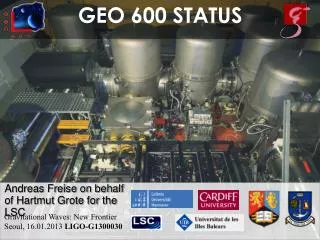
final optics 300 W at Beam Splitter test optics 2 W 1 W ~ 10 mW GEO Status July 2003 Michelson Interferometer Mode Cleaners Laser MPR MSR
with signal recycling: ModeHealing Each recycling cavity minimises the loss due to mode mismatch of the respective other power recycling only:
MSR with T=1% yields almost perfect mode healing Mode Healing Mode healing Mirror curvature compensation
Control Sidebands (SR) Resonance condition in the detuned, coupled, 4-mirror cavity: fSR= 72 ·FSRSRC 9MHz Detuning the modulation frequency and/or the demodulation phase changes the SR operating point
SRC Error Signal Example operating point for 200 Hz detuning
MI MPR MSR From Power- to Dual Recycling Optical signals change because control sidebands and higher order TEM modes experience a coupled, 4-mirror cavity. Transfer function for control sidebands must be maximised for various possible configurations: • MI arm length difference: 10 cm • cavity length difference: 9 cm
SRC Error Signal Largely detuned operating point for lock acquisition
Detuned Dual Recycling Michelson Ausgang PR Resonator Michelson Fehlersignal ESD Feedback IM Feedback SR Fehlersignal SR Feedback Zeit [s]
Power Recycling End mirrors with imperfect radius of curvature beamsplitter: „tilt“ motion