Download
1 / 32
340 likes | 360 Views
CORMIX is a powerful software for analyzing, forecasting, and designing outfall blending zones when pumping pollutants into water bodies. It features mathematical models within a user-friendly interface focusing on environmental impact assessment and regulatory compliance.

E N D
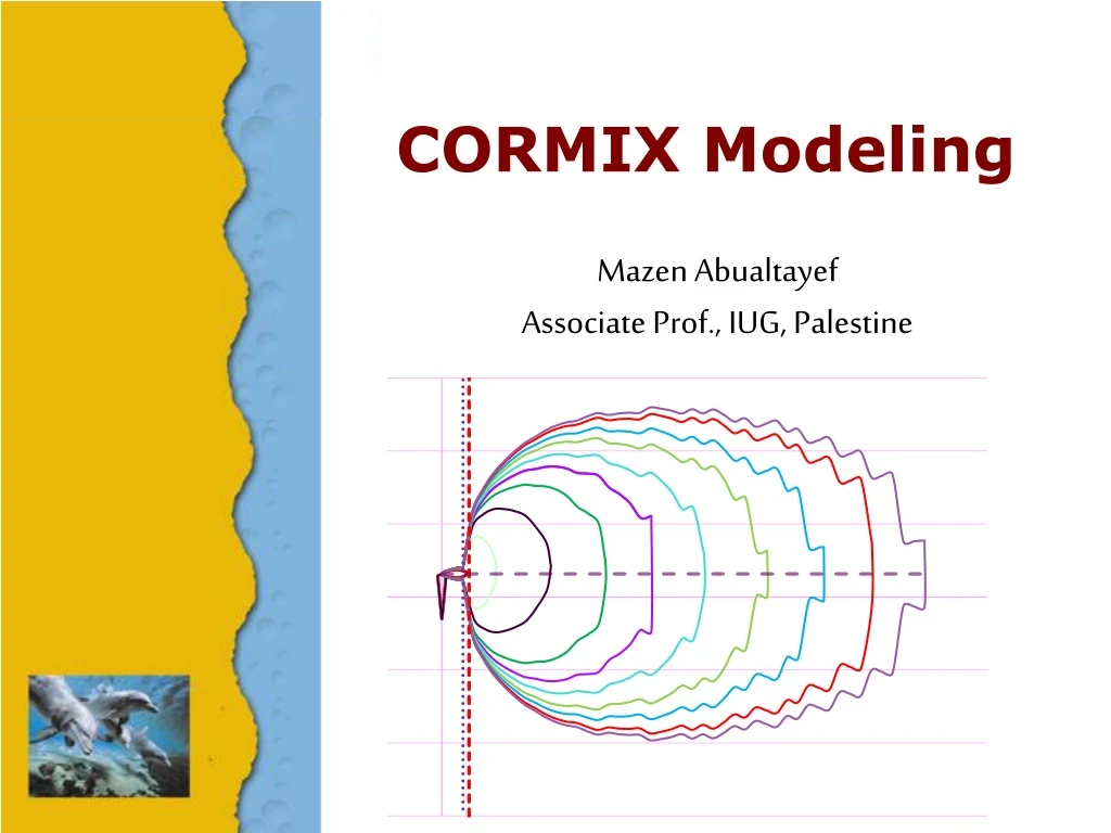
CORMIX Modeling Mazen AbualtayefAssociate Prof., IUG, Palestine
Introduction CORMIX is considering as a complete software for the analyzing, forecasting, and designing of outfall blending zones resulting from pumping of aquatic pollutants into water bodies. It consists of mathematical models of point source discharge blending within an intelligent computer-aided-design interface. It is highlight on environmental impact assessment and regulatory management (Doneker & Jirka, 2007).
Introduction CORMIX can emulate rejection process of discharges with negative, positive and neutral buoyancy, under various circumstances of discharge (single port and multiple port diffusers, emerged and submerged jets, surface discharges, etc.) and ambient circumstances (currents direction, temperature, salinity, and intensity, etc.). CORMIX is a steady state model, so time series information and statistical analyses can’t be utilize (Pilar Palomar & Losada, 2011a).
Introduction The ‘Cornell mixing zone expert system’ (CORMIX) is going to be used to simulate the behavior of the plume as a result of pumping into seawater body. The system of CORMIX computes the plume characteristics in a determined mixing zone of 100 m diameter, within which the fluid motion, turbulent field and saline dispersion are dominated by the discharge properties such as the mass flux and buoyancy flux of the outfall jet.
Introduction The hydrodynamic flow classification schemes in the CORMIX system measure the influence of potential mixing process due to momentum flux and buoyancy of the discharge, in order to predict steady state mixing zone characteristics and plume dynamics such as free jets, shoreline attached jets, wall jets and upstream intruding plumes (Jones, Nash, Doneker, & Jirka, 2007)
Conceptual Model The general ambient environment is complex and sometimes difficult to model due to complicated topographic condition. A simple configuration or schematization representing the ambient geometry is introduced in CORMIX. Other difficulties are stratified ambient and current effects which further complicated the modelling process, and therefore need some simplifying assumptions (Akar & Jirka, 1991).
Conceptual Model 1. Ambient conditions: are defined by the hydrographic and the geometric condition in the vicinity of discharge, for this purpose, a typical cross-section normal to the ambient flow direction at the discharge site and further downstream is considered. 2. Ambient geometry: for unbounded ambient CORMIX assume an equivalent cross-sectional area that is defined by depth, by distance from bank to the discharge position, wind speed, and by ambient velocity.
Conceptual Model 3. Ambient current: CORMIX assumes a uniform ambient current, it does not deal with complicated representation of current patterns, including shear effects and other non-uniformities, therefore an average seasonal ambient velocity is preferred to employ. 4. Stratification effects: a variation of density with respect to the depth is common in many water bodies. Although ambient density stratification plays an important role in discharge design, a uniform seasonal density water body over four seasons is recommended.
Study Area Domain The study domain is ??km longshore times ??km cross-shore, where the seabed depth is varying from 0m at shoreline to ??m at 200m offshore (proposed outfall location) and around ??m at 1km offshore. CORMIX simulation results are with: space scales of 10-2 to 104 m and time scales of 10 to 105 seconds.
Boundary Conditions The boundary conditions are representing in unbounded ambient with equivalent cross-sectional, where open boundaries are defined by distance from shoreline to the discharge position and by ambient velocity and tide, while the shoreline is defined according to the ambient direction (left or Right), the surface is defined by wind speed and the bottom is defined by depth at the discharge, seabed slope, and roughness characteristics representing in Darcy-Weisbach friction factor, see the following figure:
Initial and Input Conditions • Bathymetric filed survey • Seawater characteristics • Seawater quality [1] Black and Veatch (2016). Marine survey for the expansion of the existing desalination plant in Deir Al Balah.The presented numbers are constant due to a single site-specific reading in March 2016.TSS is not expected to significantly change seasonally.[2] Fichtner (2015). Marine survey for Gaza central desalination plant.[3] Israel Oceanographic and Limnological Research IOLR (2016). Seawater characteristics at Ashkelon.[4] Ministry of Agriculture (2016). Deir Al Balah meteorological data for 2015-2016.[5] IOLR, Israel Marine Data Center, Israel oceanographic and limnological research, [Online].
Initial and Input Conditions 2. Seawater characteristics 2. Currents Tidal currents within the Eastern Mediterranean Sea are in general weak. The general circulation, mainly due to the geostrophic current and shelf waves, is oriented counterclockwise most of time. The currents in most cases have low speeds of about 0.10 m/s and the current speed decreases towards the shore. In certain instances, currents of about 1.00 m/s have been measured (Rosen, 2001). Typical current mean velocities are 0.05–0.10 m/s, and there is a clear bimodal seasonal signal, with the strongest mean northward flow in February and July, and the weakest northward flow in May and September (Brenner, 2003). Ashkelon current rose for 2012-2015 Source: (IOLR)
Initial and Input Conditions 2. Seawater characteristics 3. Tides The effect of meteorological variations on sea level may often be greater than astronomical tides. In the Mediterranean, the combined effect of barometric pressure variations, storm surges and waves can reach values which are of the same order as the tidal variations. (MEA-PNA, 2002). HAT: Highest astronomical tide; MHWS: Mean high water in spring; MHWN: mean high water in neap; MSL: Mean sea-level; MLWN: Mean low water in neap; MLWS: Mean low water in spring; LAT: Lowest astronomical tide.
Initial and Input Conditions 3. Characteristics of the disposed BRINE [1] UG and Arterlia Consultants, 2013. Preliminary design for Short-Term Low Volume (STLV) Seawater Desalination for Southern Governorates of Gaza Strip. [2] Brine sample characteristics, tested by CMWU Coastal Municipalities Water Utility,22/4/2019 [3] Brine sample characteristics, tested by water lab at Islamic University of Gaza,21/5/2019
Initial and Input Conditions 4. Excess concentrations
Initial and Input Conditions 5. Regulatory mixing zone UNEP environmental standards and regulations are recommended. UNEP regulations on the discharge of liquid waste into the marine environment characterize the mixing zone as a circle with a diameter of 100 m centered at the disposal point.
Model Validation CORMIX is supported by the US-EPA as a valid tool to analyze marine outfall mixing areas caused by polluted effluents discharged into a water body (Purnama et al., 2003). Extensive comparison with field and laboratory data has shown that the CORMIX predictions on dilutions and concentrations are reliable for the majority of cases (MixZon Inc, 2017).
Brine Diffuser Scenarios • Offshore discharge submerged single-port diffuser • Offshore discharge submerged Multiport diffusers • Alignment angle (g) is the angle between diffuser line and ambient current, measured counterclockwise from the ambient current direction (x-axis). • Vertical angle (q) is the angle of the nozzle/port discharge centerline above the horizontal plane. • Horizontal angle of discharge (sis the angle measured counterclockwise from the x-axis (ambient current direction) to the average port/nozzle centerline direction. • Relative orientation angle (b) is the nearest angle between the horizontal projection of the average port/nozzle centerline direction and the diffuser axis.
Brine Diffuser Scenarios Single port outfall
Brine Diffuser Scenarios Multiport Diffusers
Brine Diffuser Scenarios Alternating multiport diffuser
Brine Diffuser Scenarios Unidirectional multiport diffuser- same direction
Brine Diffuser Scenarios Unidirectional multiport diffuser- Fanned-out
Brine Diffuser Scenarios Staged multiport diffuser
Configuration Design of the Offshore Disposal Systems The key objective of a brine outfall diffuser is to dilute the brine effluent in accordance with the relevant marine water quality guidelines, the design of diffuser should consider discharging angle, appropriate diameter, discharging velocity, Froude number, Reynolds number and Ports spacing. The optimum design would have to incorporate the requirements and still be feasible in terms of manufacturing, installation, operational requirements and subsequently the associated costs.
Configuration Design of the Offshore Disposal Systems- Discharge angle Christodoulou et al. (2015) indicate that the practical range for discharge angel is between 30˚ and 75˚. In deep waters, it is advisable to maintain high inclination angle range 60˚ to 75˚, while in shallow waters, a range from 30˚ to 45˚ is preferred to achieve satisfactory results.
Configuration Design of the Offshore Disposal Systems- Port spacing The spacing is a dynamically unimportant variable that has a limited effect on overall mixing. However, the spacing plays a role in the merging process of the individual jets/plumes, and thus may affect the very initial mixing, e.g. as of interest in toxic dilution zone (TDZ) predictions. As a rough rule, merging takes place after a distance along the plume path of about 3-5 spacings (MixZon Inc, 2017).
Configuration Design of the Offshore Disposal Systems- Froude number The Froude number is expressed as the following equation: Where: D is the pipe diameter, uo is the mean velocity, and g0 is the buoyant acceleration. The Fr0 should be ≥10. For smaller Fr0, the initial dilution becomes lower. Furthermore, it is recommended that the Fr0 be in the range of 20 to 25 (Jirka, 2008).
Configuration Design of the Offshore Disposal Systems- Reynolds number The Reynolds number, is expressed as following equation: Where: D is the pipe diameter, V is the mean velocity, and n is the kinematic viscosity of the fluid. For appropriate design the Re0 must be ≥4000 to ensure maintain turbulent flow, as turbulent flow achieve better dilution.
Configuration Design of the Offshore Disposal Systems- Discharging velocity and diameter Much better mixing efficiencies can be achieved with high-velocity discharges ports (Jirka, 2008). A range of 4-6 m/sec for maintaining Froude number and Reynolds number larger than 10 and 4,000, respectively is recommended by discharge calculator. A rule of thumb for the continuity of flow is that the total cross-sectional areas of the ports should not be less than 0.7 times the cross-sectional area of the main pipe at any point in the diffuser (Le Roux, 2010).