Download
1 / 47
470 likes | 581 Views
Discover the fundamentals of mechanical engineering including types of links, degrees of freedom, guiding controls, adhesion, friction, and motion transmission systems in technical objects. Learn key concepts and examples for a comprehensive understanding.

E N D
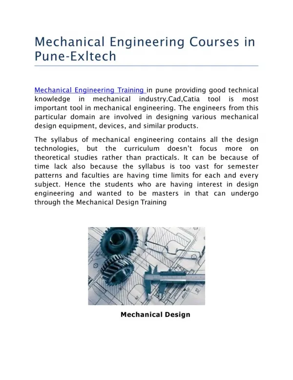
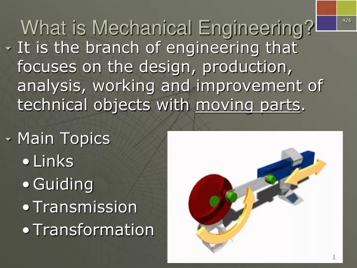
What is Mechanical Engineering? • It is the branch of engineering that focuses on the design, production, analysis, working and improvement of technical objects with moving parts. • Main Topics • Links • Guiding • Transmission • Transformation
Please write this! 13.0 Linking in Technical Objects • Linking is the mechanical function performed by any component that connects different parts of a technical object. • You MUST know how to describe the types of links! • p428.
Direct OR Indirect Link between the wheel & the frame. Link between the wheel & the chassis.
Rigid OR Flexible Link between the wheel & the frame. Link between the wheel & the chassis.
Removable OR non-removable • Partial OR Complete Link between the wheel & the frame. Link between the wheel & the chassis.
Please write this! Examples Link between the wheel & the chassis. • Indirect • Rigid • Removable • Partial Link between the wheel & the frame. • Direct • Flexible • Removable • Complete
Please write this! 13.1 Degrees of Freedom of Movement • are the set of independent movements that are possible for a given part in a technical object.
Please write this! • The motion can be: • Translational (back & forth) • Rotational • Which axis? • X (horizontal), • Y (vertical), or • Z (out at you!) • Notation – 6 possible degrees of freedom Tx, Ty, Tz, Rx, Ry, Rz
Please write this! • Example: a regular door • can only rotate around the hinges 1 degree freedom Ry • See p429 chart
Examples Rx Tx Ry & Ty
Guiding Controls • A Guiding Component or Control is a component that guides the motion of moving part.
Please write this! 13.2 Types of Guiding Controls • Translational Guiding ensures the straight translational motion of a moving part. • E.g. a vertical window groove
Please write this! • Rotational Guiding ensures the rotational motion of a moving part.E.g. a bicycle wheel hub
Please write this! • Helical Guiding ensures the translational motion of a moving part while it rotates about the same axis. • E.g. threaded screw.
Please write this! 13.3 Adhesion and Friction of Parts • Adhesion = two surfaces remain in contact with each other without slipping. • Friction is a force that resists the slipping • Lubrication is the mechanical function performed by any component that reduces friction between two parts. Phone book demo & Mythbusters click-here
Please write this! 5 Factors affecting friction • Nature of materials (eg: steel on asphalt vs. rubber on asphalt) • Presence of a lubricant (water, oil, wax) or adhesive (glue) • Temperature: the colder the temperature the less the adhesion • Surfaces (rough vs. smooth) • Mass of the object (a heavy object will have better adhesion, more friction) SURFACE AREA does NOT affect friction! Remember P = F/A
Please write this! 13.4 Motion Transmission Systems • Motion Transmission relays motion from one part to another without altering the nature of the motion. • A Motion Transmission System is a set of parts that transmit motion.
Please write this! • Driver component: receives the force required to activate the system Eg: Pedal gear on a bike • Driven component: receives the motion and transfers it to another part Eg: rear gears on a bike • Intermediate component: located between the driver and driven component not all systems have this. Eg: the chain on a bike
Please Write ONTO handout • Common rotational transmission systems: • Gear Train System • Chain and Sprocket Systems • Worm and Worm Gear Systems • Friction Gear Systems • Belt and Pulley Systems • Use text p437 when studying!
1. Gear Train System • The direction of rotation alternates from one wheel to the next. • Yes ! It is reversible.
Other information – Gear Trains • Gear teeth: all the gear teeth in a system must be identical – same shape, direction, size & be equally spaced. E.g. Straight or helical or beveled
The rotational axis of the gears can be positioned different ways • eg: car differentials • Gear size: Larger gears (with more teeth) rotate slower. Smaller gears rotate faster.
2. Chain & Sprocket Systems • The direction of rotation: Sprockets turn in the same direction when they are located on the same side of the chain (opposite on the other side of the chain) • It can be reversed. • Larger = slower • Smaller = faster • Requires frequent lubrication
3. Worm & Worm Gear Systems • The direction of rotation depends on the direction of the threads on the worm screw axle. • It is not reversible. • Worm screwmust be the driver! • Larger worm gear = slower rotation
4. Friction Gear Systems • The direction alternates from one gear to the next. • It is reversible. • Smaller = faster • Larger = slower Same as gear trains
ADD TO OTHER INFO! • Friction gear systems are similar to gear trains except that motion is transferred by FRICTION and not by the GEAR TEETH. • They are less efficient, they tend to slip at times. • Friction is affected by • gear type (straight or beveled), • gear size& • choice of material.
5. Belt and Pulley Systems • Similar to the chain and sprocket system. • The chain is replaced by a belt. • The sprocket is replaced by a pulley. • The choice of the belt material and the tightness of the belt affect the friction and hence the efficiency of the system. • The direction is the same for any pulley on the same side of the belt. • It is reversible. • Smaller = faster • Larger = slower
Speed Changes in Motion Transmission Systems • A Speed Change occurs when the driver does not turn at the same speed as the driven component(s). • The speed change depends on the size ratio of the driver compared to that of the driven component.
Please write this! 13.5 Speed Changes in Motion Transmission Systems • You can compare: • # of teeth • Diameter • Circumference • Speed ratioDriver = 15 mm = 3 = 3 or 3:1 Driven 5 mm 1 So the driven pulley turns 3 times FASTER than the driver.
Please write this! To increase the speed, the driven component should have a smaller diameter. driver driven To decrease the speed, the driven component should have a larger diameter. driver driven To keep the same speed, the two pulleys should have the same diameter.
Calculating Gear Speed Ratios Please write this! Ex. 1 Driver (A) = 60 Driven (B) 30 Driven is twice as fast! If A is turning at 22 rpm, how fast is B turning? 22 rpm x 2 = 44 rpm (more examples p443) = 2 1 = 2 speed ratio is 2:1 Reduce the fraction
Please write this! Reduce the fraction A= 20 B 80 = 1 = 0.25 4 • Ex. 2 Speed ratio 1:4 If A is turning at 60 rpm how fast is B turning? 60 rpm x 0.25 = 15 rpm B rotates at a speed ¼ that of A = A turns 4 times faster than B
Please write this! Speed Changes in Worm & Worm Gear Systems • Larger worm gear= greater decrease in speed. • Smaller worm gear = smaller decrease in speed. • 1 turn of the worm = the worm gear will rotate by the width of 1 tooth! speed ratio = 1 #of teeth in worm gear • See p442
13.6 Torque Please write this! • Torque involves 2 equal forces in opposite directions. • Causes rotation • Engine Torque increases the rotational speed of components • Power from engine • Resisting Torque slows or stops the rotation • caused by friction, air resistance, gravity
Please write this! Torque and Speed Change engine torque = resisting torque, No speed change engine torque > resisting torque, speed increases engine torque < resisting torque, speed decreases
Gear mechanism in natural world By University of Cambridge (Profs. Malcolm Burrows & Gregory Sutton) - http://www.cam.ac.uk/research/news/functioning-mechanical-gears-seen-in-nature-for-the-first-time, CC BY-SA 3.0, https://commons.wikimedia.org/w/index.php?curid=38215934 In 2013scientist from the University of Cambridge discovered a common European insect, Issus coleoptratus. I has a gear-like mechanism in its hind legs. The joint rotates like mechanical gears and synchronizes Issus's legs when it jumps. By Sarefo - Own work, GFDL, https://commons.wikimedia.org/w/index.php?curid=7012881
Fill in table as we go! 13.7 Types of MOTION TRANSFORMATION Systems • Relays motion by changing the type. • Translation Rotational • The most common systems are: • Rack and Pinion • Screw Gear Type 1 • Screw Gear Type 2 • Cam and Followers • Slider-Crank systems
1. Rack and Pinion Systems • Convert rotational translational • “Rack” = straight bar with teeth. • “Pinion” = the gear. • Used in steering systems. • Larger the pinion = slower the rotation
2 & 3 Screw Gear Systems • Converts rotation to translation • The screw gear uses a threaded bolt to move another gear or itself. • Not reversible
Screw Gear Type 1 • Screw is the driver • Car Jack
Screw Gear Type 2 • Nut is the driver • Pipe wrench
4 Cam and Followers • Converts rotational to reciprocating (back and forth) translational motion • Eg. A sewing machine
Eccentric Cams • Rotational axis of an eccentric cam is off center, p. 449 Please write this!
5 Slider-crank System • Converts rotation translation • Used in car engines • The slider is the piston. • The crank attaches the piston to a wheel. • Usually the slider is the driven component.