Download
1 / 10
110 likes | 278 Views
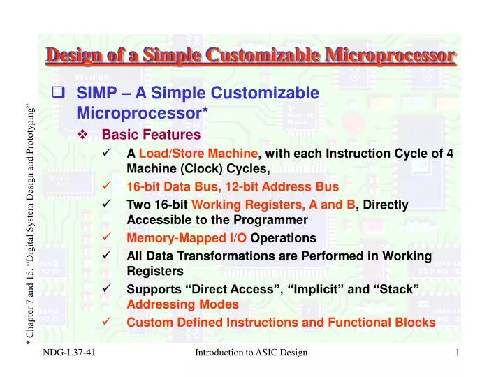
Design of a Simple Customizable Microprocessor. SIMP – A Simple Customizable Microprocessor* Basic Features A Load/Store Machine , with each Instruction Cycle of 4 Machine (Clock) Cycles, 16-bit Data Bus, 12-bit Address Bus

E N D
Design of a Simple Customizable Microprocessor • SIMP – A Simple Customizable Microprocessor* • Basic Features • A Load/Store Machine, with each Instruction Cycle of 4 Machine (Clock) Cycles, • 16-bit Data Bus, 12-bit Address Bus • Two 16-bit Working Registers, A and B, Directly Accessible to the Programmer • Memory-Mapped I/O Operations • All Data Transformations are Performed in Working Registers • Supports “Direct Access”, “Implicit” and “Stack” Addressing Modes • Custom Defined Instructions and Functional Blocks * Chapter 7 and 15, “Digital System Design and Prototyping” Introduction to ASIC Design
Design of a Simple Customizable Microprocessor • SIMP – A Simple Customizable Microprocessor* - Cont’d • Programmable Model– User Directly Accessible Registers • Invisible Registers: PC, SP, TEMP, and ST * Chapter 7 and 15, “Digital System Design and Prototyping” Fig-01: SIMP Programming Model Introduction to ASIC Design
Design of a Simple Customizable Microprocessor • SIMP – A Simple Customizable Microprocessor* - Cont’d • Instruction Set and Instruction Format – All Instructions are 16-bit wide (One Memory Word) • Direct Addressing Mode: 4 MSBs represent OPCODE and 12 LSBs represent Memory Address • Implicit or Stack Addressing Mode - * Chapter 7 and 15, “Digital System Design and Prototyping” Introduction to ASIC Design
(cont’d) Design of a Simple Customizable Microprocessor • SIMP – A Simple Customizable Microprocessor* - Cont’d • Instruction Set and Instruction Format – Cont’d * Chapter 7 and 15, “Digital System Design and Prototyping” Introduction to ASIC Design
Design of a Simple Customizable Microprocessor • SIMP – A Simple Customizable Microprocessor* - Cont’d • Instruction Set and Instruction Format – Cont’d • Memory Reference Instructions – Direct or Stack Addressing Mode (Depending on Bit-15) * Chapter 7 and 15, “Digital System Design and Prototyping” Introduction to ASIC Design
Design of a Simple Customizable Microprocessor • SIMP – A Simple Customizable Microprocessor* - Cont’d • Instruction Set and Instruction Format – Cont’d • Other SIMP Core Instructions – All Implicit Mode * Chapter 7 and 15, “Digital System Design and Prototyping” Introduction to ASIC Design
Design of a Simple Customizable Microprocessor • SIMP – A Simple Customizable Microprocessor* - Cont’d • SIMP Datapath Fig-02: SIMP Datapath * Chapter 7 and 15, “Digital System Design and Prototyping” Introduction to ASIC Design
Design of a Simple Customizable Microprocessor • SIMP – A Simple Customizable Microprocessor* - Cont’d • SIMP Control Flow – Fetch (T0/T1), Decode (T2), Execute (T3) * Chapter 7 and 15, “Digital System Design and Prototyping” Fig-03: SIMP Control Flow Diagram Introduction to ASIC Design
Design of a Simple Customizable Microprocessor • SIMP – A Simple Customizable Microprocessor* - Cont’d • SIMP Instruction Execution Flowchart Fig-04: Instruction Execution Cycle * Chapter 7 and 15, “Digital System Design and Prototyping” Introduction to ASIC Design
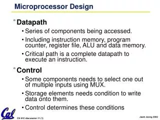
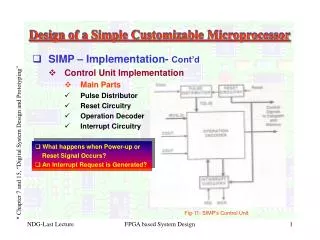
Design of a Simple Customizable Microprocessor • SIMP – A Simple Customizable Microprocessor* - Cont’d • SIMP Implementation – Datapath + Control Unit • Datapath consists of all registers + interconnect structures (such as Muxes) and ALU etc. • Control Unit provides proper timing, sequencing, and synchronization of micro-operations, other activation signals + control signals for external world * Chapter 7 and 15, “Digital System Design and Prototyping” Fig-05: Basic Partition of SIMP Design Introduction to ASIC Design