Download
1 / 23
230 likes | 409 Views
Quench Protection for Very High Field Magnets using HTS Conductors. Stephen Kahn Muons Inc. NFMCC UCLA Meeting 1 February 2007. HTS Magnet Protection—Why is this different from normal Quench Protection?.

E N D
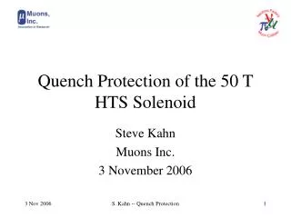
Quench Protection for Very High Field Magnets using HTS Conductors Stephen Kahn Muons Inc. NFMCC UCLA Meeting 1 February 2007 S. Kahn -- Quench Protection
HTS Magnet Protection—Why is this different from normal Quench Protection? • In our scenario for a muon collider we (casually) use very high field magnets that can not be achieved using normal Niobium superconductors. • The NbTi alloy is a ductile material that has reasonably decent mechanical properties. • Reasonable current to 7T at 4.2 K • Nb3Sn superconductor is a more brittle material. Fields to ~17 T. • It has been demonstrated that HTS conductor can carry significant current at fields as high as 45 T • HTS conductor is very brittle. There is a major concern about damage from strain. S. Kahn -- Quench Protection
HTS coils Nb3Sn coils NbTi Coils R, m Recent Model of 50 T Solenoid (LTSW06) S. Kahn -- Quench Protection
Comparison of High Field Solenoid Parameters S. Kahn -- Quench Protection
Two Concerns with HTS Magnets • One concern is how to remove this large amount of energy from the magnet in case of an incident. • The second concern is that the quench propagation velocity for HTS is very slow. The superconductor can heat up significantly before the quench energy can spread. • This can cause local irreversible damage to the magnet. S. Kahn -- Quench Protection
Conductor and Insulator Description • The conductor is BSCCO 2223 which is 30% HTS filaments and 70% Ag matrix and Ag-Mg sheath (for strength). We assume the matrix/sheath is all Ag for the calculation. • The insulator is assumed to be the Stainless Steel interleaving. A minimum thickness (0.07 mm) is used since we are describing the inner layers. • In practice we will likely add a ceramic coating or kapton wrap as insulator. This will inhibit the transverse quench propagation. S. Kahn -- Quench Protection
Conductor Material Properties Necessary for Quench Protection • We need the material properties of all the components of the conductor and insulation. • The important properties are • Heat capacitance (Specific Heat) • Resistivity • Thermal conductance • Obtained from resistivity with Wiedemann-Frantz law. • CV and are parameterized as in up to four temperature ranges: S. Kahn -- Quench Protection
Conductor Material Properties Necessary for Quench Protection • We need the material properties of all the components of the conductor and insulation. • The important properties are • Heat capacitance (Specific Heat) • Resistivity • Thermal conductance • Obtained from resistivity with Wiedemann-Frantz law. • CV and are parameterized as in up to four temperature ranges: S. Kahn -- Quench Protection
Critical Current, Field, and Temperature Measurements on BSCCO 2223 Conductor Data from EHTS Bi-2223 Data Sheets. Measurements were performed at GHMFL, France. 4.2 K S. Kahn -- Quench Protection
Critical Current Measurements Used only high field part of data to determine Bc20 • Measurements of critical current as a function of B and temperature are from EHTS (another provider of BSCCO 2223). • The measured data is used to determine parameters of the following equation: This formula is used for NbTi and Nb3Sn. Is it valid for HTS?? S. Kahn -- Quench Protection
Maximum Field Operating Field HTS Characteristics: JC vs. B for Constant T 0.85 Contingency factor S. Kahn -- Quench Protection
T1 Ts T0 Lorentz Number Quench Propagation Velocity • Quench protection calculations depend on the quench propagation velocity. • The quench propagation velocity can be calculated from the formula below. • This is what I did. • Experience for NbTi shows that the formula does not reproduce the measurements. • Typically the experimentally determined value is used. • We need to measure this for HTS. • One of the weaknesses of the velocity calculation is that the specific heat (CV) varies as T3 and is rapidly varying at the quench front. S. Kahn -- Quench Protection
Comments on Quench Velocity Measurements • The quench propagation velocity in this experiment is ~4 cm/sec. In NbTi it is approximately 1 m/sec. • If a quench occurs and the heat can not be dissipated, the local area will heat up to a very high temperature. It can be destructive. • The slow propagation velocity is largely due to the fact that at 4.2°K most of the SC is far away from the critical temperature. • The closer we are to the critical condition, the faster the quench velocity. • Restated: A conservative design with a large safety factor built-in against quenches occurring could be self-destructive if a quench does occur. • The typical approach used with NbTi and Nb3Sn of firing heaters to make the magnet go normal faster won’t work. • It takes too much external energy to make the magnet go normal and would likely increase the destruction. S. Kahn -- Quench Protection
Preliminary Calculations • I am presenting some preliminary calculations using the quench calculation program QUENCH. • This program was written by Martin Wilson at Rutherford Lab in the 1970’s. The current version of the program is marketed by B. Hassenzahl of Advanced Energy Analysis. BNL has a license to use it. • There are other codes available: • QUENCHPRO at FNAL Technical Division. • SPQR from CERN. • QLASA from INFN-Milano. • QUABAR. • Vector Fields is developing a quench propagation code. • Being beta tested now. S. Kahn -- Quench Protection
Power Supply RSW RPR L REXT Circuit for Quench Energy Extraction • Quench circuit components: • Solenoid represented by inductance L. Also there is an internal resistance (not shown) which is about 10 ohm. • RPR represents the energy extraction resistance. This will take the large share of quench energy. • Switch will be activated by quench detection system. • Could even be a diode system. • REXT represents the resistance associated to leads, power supply, etc. Solenoid Magnet S. Kahn -- Quench Protection
Circuit Parameters • QUENCH treats the whole magnet. It does not provide for segmenting the magnet into separate coupled systems. • This means that the current has the same time-dependence throughout. • We shall ignore the Nb3Sn outer coils. • We assume that they are sufficiently away from critical that they won’t quench. Also that the Nb3Sn coils will not affect the HTS (this may be a bad assumption). • The total inductance can be calculated from the stored energy: • U=½LI2 where U=66 Mega-Joules and I=129 amps is the single turn current. • There are 672 layers 250 turns/layer = 167821 turns. • This gives 8000 henrys (big!) • The resistance associated with 61 km of Ag is 8 ohms. • We certainly will need to trigger an external resistance into the circuit with a quench is detected. S. Kahn -- Quench Protection
Quench Simulation • We want to ramp the magnet down with a single time dependence. (This is all that Quench can do) we would like to segment the magnet into separate circuits with diodes. • This provides greater sensitivity to quench incidents. • This will prevent unreasonably large voltages across external resistances. • Each sub-circuit consists of two adjacent conductor layers. • Quench detection circuitry can be put on one end of the magnet. • IGBT switches to include external resistance circuit when the quench is detected. S. Kahn -- Quench Protection
Quench Parameters as a Function of External Resistance • The figures show the following parameters • as a function of an external resistance for • energy extraction. • Maximum temperature on conductor • Time constant for decay • External voltage on external resistance • Note that as one increases the external • resistance one decreases temperature, but • increases the external voltage. S. Kahn -- Quench Protection
Quench Detection • Typical quench detection circuits used for LHC and the 25 T NHMFL Solenoid(with HTS insert) trigger at 200-250 mV. • This corresponds to ~4 cm of “Ag resistance” or 1 sec detection time. • A “back of the envelop” calculation of T gives ~150°K. • Caveat: Cv varies as T3 so one needs to do a proper integration over time which can change this significantly. • We would like to keep T < 200°K if possible to avoid potential damage to the conductor (from micro-cracking) • If we can detect a quench at 0.1 sec (trigger at 10-25 mV) we would gain significantly. • We anticipate that the time constant to remove the field to be ~1-10 sec. S. Kahn -- Quench Protection
An Alternate Approach to Remove Energy This idea was suggested by R. Flora. • When a quench occurs, the detection circuit triggers some of the dump resistors. • Energy is transferred to adjacent coils inductively such that they will induce a quench in those coils. • The dump resistors of the remaining coils are turned on. • This approach would spread the quench throughout the magnet without adding energy from external sources as heaters. This should permit a faster ramp-down of the magnet in a controlled manner. S. Kahn -- Quench Protection
A Program to Study Quench Protection for HTS Magnets • Muons Inc has submitted an SBIR proposal with Fermilab to study protection of HTS magnets. • We would like to setup a test station to study quench detection of HTS magnets. • We would like to investigate techniques to detect quenches in ~10 ms with amplitudes of ~10 mV. • It is clear from this initial calculation that some parameters are not well known. We should try to measure them. • Electrical resistivity and heat capacity of HTS conductor as a function of temperature. This should be done above critical current. • Same measurements of Silver as a control. • Determine Ic(B) at high field. Verify that the critical current relation that we used (which was developed for NbTi, Nb3Sn) works for HTS. • Measure the quench propagation velocity. This is important. S. Kahn -- Quench Protection