Download
1 / 10
110 likes | 262 Views
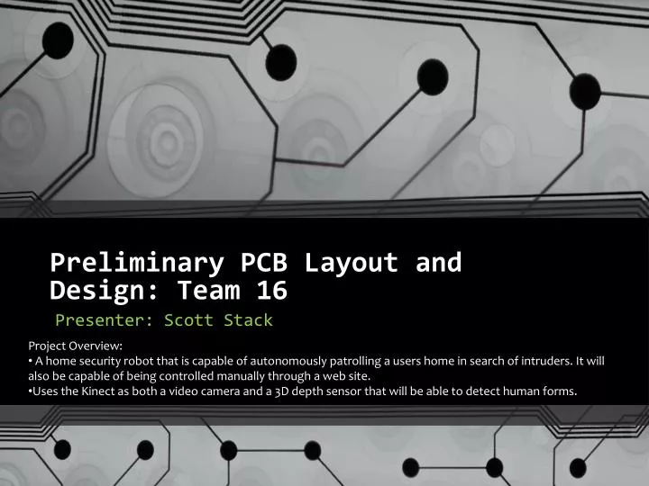
Preliminary PCB Layout and Design: Team 16. Project Overview: A home security robot that is capable of autonomously patrolling a users home in search of intruders. It will also be capable of being controlled manually through a web site.

E N D
Preliminary PCB Layout and Design: Team 16 • Project Overview: • A home security robot that is capable of autonomously patrolling a users home in search of intruders. It will also be capable of being controlled manually through a web site. • Uses the Kinect as both a video camera and a 3D depth sensor that will be able to detect human forms. Presenter: Scott Stack
Overall Layout Constraints • Two separate PCBs : One for battery fuel gauge and one main board • Fuel gauge must be powered at all times. • Four separate power supply circuits 3.3V, 5V, 7.2V, 12V • All linear switching regulators that require carful layout • Wide traces for heavy current flow • Isolation of high current circuits from digital logic • 12 volt for atom board and Kinect up to a maximum of 3A • 7.2 volt for motors up to an absolute maximum of 4A (typical ~400mA) • Enough board space to accommodate external connectors • RS232 header, 0.1” headers, RJ-11 jack, 2 barrel connectors • Pad out unused pins on microcontroller • Main board must be smaller than 10”x10” to fit on chassis • Fuel gauge PCB must be as small as possible