Download
1 / 23
230 likes | 415 Views
Advanced Hardware Technology In ALMA Back End And Correlator. Fabio Biancat Marchet (1) – fmarchet@eso.org Alain Baudry (2) – Alain.Baudry@obs.u-bordeaux1.fr European Southern Observatory (ESO), Munich, Germany Observatoire Aquitain des Sciences de l’Univers de Bordeaux, Bordeaux, France.

E N D
Advanced Hardware Technology In ALMA Back End And Correlator • Fabio Biancat Marchet (1) – fmarchet@eso.org • Alain Baudry (2) – Alain.Baudry@obs.u-bordeaux1.fr • European Southern Observatory (ESO), Munich, Germany • Observatoire Aquitain des Sciences de l’Univers de Bordeaux, Bordeaux, France
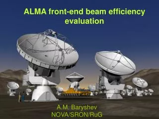
The ALMA Project: Atacama Large Millimeter Array ALMA is an international astronomy facility. It is an equal partnership between Europe and North America, in cooperation with the Republic of Chile, and it is funded in North America by the U.S. National Science Foundation (NSF) in cooperation with the National Research Council of Canada (NRC), and in Europe by the European Southern Observatory (ESO) and Spain. ALMA construction and operations are led on behalf of North America by the National Radio Astronomy Observatory (NRAO), which is managed by Associated Universities, Inc. (AUI) and on behalf of Europe by ESO. • ALMA will provide unprecedented performances in the sub-millimeter range for the study of cold objects, representing the natural complement of the next generation of ground and space based facilities operating in the optical-infrared domain. • ALMA full operation is planned for 2011 • The observatory is designed to operate for 3 decades • It will be composed by >50 12m Antennas • The overall collecting Surface will exceed 5000 m2 • The Antennas can be relocated among > 170 locations to accommodate different types of observations with: • A compact Configuration ~150m diameter • An extended Configuration ~14km diameter
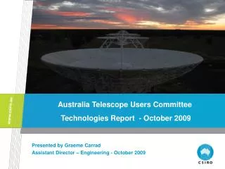
The Site • Atacama Desert, Northern-Chile • Plateau de Chajnantor at 5000m altitude • Observation Window: [30GHz, 1THz] in 10 bands • Example : Band 9 : 602 – 720GHz Band 10 : 787 – 950GHz • Location selected for the extremely good Atmospheric properties • Drawbacks: low air density (<50%), lack of oxygen, remote • Consequently Operations at site severely limited impose: • High Reliability (proven technologies, low thermal stress) • Line Replaceable Unit (LRU) approach • Remote diagnostics
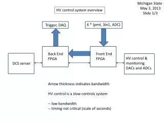
The Instrument Back End Front End Correlator Computing Spectral Density Frequency Down-conversion BE/Correlator Custom Developments Sampling + Quantization LO Photomixers Digital Filtering + Correlation Digitizer ASICS DFT Correlator ASICS
The Instrument Antenna Side Technical Building Side Front End Back End Antenna Correlator 10 Cryogenic Cartridges Back End Front End Antenna Cryogenic Vessel Computing • Cryogenic Receiver (one cartridge for each band) • Conversion into the 4-12GHz band, two polarizations • Digitization Transmission of the data to the TB • Filtering • Correlation • Post-Processing
BE IF Processor Back End Front End Correlator Computing • Input 8GHzBand split in 4*2-4GHz sub-bands (two polarizations)
Data Transmission System (DTS) Back End Front End Correlator Computing • Digitization 4Gsamples/s, 3 bits * 8 Channels • Each channel De-multiplexed to 3* 16-bit parallel streams @250 MHz • Further formatting converts to 12*10Gb/s serial streams • Each driving a laser emitter with different “color” (DWDM) • All 12 light beams mixed in one single fibre • Net data rate from one Antenna: 96Gb/s (120GB/s coarse)
The Photonics Local Oscillator • Interferometric Operation of the Array requires extremely accurate phase reference. The Reference shall be distributed synchronously to the Antennas with a phase stability within 50fs. • Two laser beams are phase-locked and distributed by a single fibre to the Antennae • At the Antenna the beams are mixed to obtain the frequency-difference signal (in the range 27-142GHz) as Local Oscillator source for the Heterodyne Receivers • In order to compensate for Fibre length variations an interferometric Line Length Corrector is implemented that measures the round-trip time and acts on a Fibre Stretcher to compensate for length variations
The Photomixer The key component performing the conversion of the incoming light beams in a signal whose frequency is the difference is the Photomixer Block The Photomixer Block is based on a commercial photodiode which is thinned/cut to match the high frequency requirements and packaged in a precisely machined case that provides the optical and electrical connections and the output waveguide/filter. The device has been designed and manufactured at Rutherford Appleton Labs (UK).
The Digitizer Assembly • The Digitizer assembly within the Data Transmission System digitizes • a pair of 2-4GHz input signals at 4GHz sampling rate with 3-bit resolution. • Each bit stream is then de-multiplexed into one parallel 16-bit stream at 250MHz • There are 4 Digitizer assembly in each Antenna • Sampling/Digitization is performed by the custom Digitizer chip VEGA • De-multiplexing is performed by the custom De-multiplexer chip PHOBOS
DFFs Comparators D-Latches Input Amplifier Clock Amplifier ALMA : VEGA the Digitizer • Flash Architecture: 7 comparators, 8 levels, 3 bits • Technology: BiCMOS 0.25µm SiGe (2.5V) • Input: 2-4GHz (Gaussian noise) • Sampling clock: 4GHz • Output: differential (LVDS) • Output Gray code • Self clock feature for easy test • Power dissipation: 1.5W • Bandwidth ripple <0.5dB • Packaging is an issue • Special High Frequency with low thermal resistance and thermal drainVFQFPN 44 7x7x1mm • Ball-bonding • Parasitic elements : • Bonding : inductance ~1nH/mm • pad capacitance : ~0.3pF
ALMA : PHOBOS the De-multiplexer Basically a shift-register that De-serializes 4 Gb/s into 16 bits @250MHz Simplified block Diagram (1:4) • Same technology as VEGA, more complex layout, but less critical being full digital: • BiCMOS 0.25µm en SiGe (2.5V) • Input : LVDS) • Clocks: 4GHz et 250MHz • 16 differential outputs @ 250MHz • Power dissipation 1.5W S0 S1 S2 S3 D2 4GHz Clock buffer 250MHz Clock buffer • Packaging • Difficult at the beginning: suitable package unavailable: direct bonding on PCB tried but yield rather poor (60%) • Then VFQFPN 68 10x10x1mm became available
Digitizer Chips Development • The ASICS have been fully designed at UB (Observatoire and IXL labs) • Synthesis, analysis and simulation tools provided by STm • Sample production with Multiple Project Wafer service to reduce costs • Three Digitizer and two De-mux test versions before the final fully engineered ones • Overall cost ~1.6 MEur (50% for NRE) • Development time ~3 years • Series production complete (~1000 ADC and 3000 Demux produced)
Why ASIC? • Operation speed and power consumption required a custom development for both chips, not existing on the market any device fully matching the requirements. • The most critical one is the Digitizer, the market offers devices with comparable performances in terms of speed/resolution, however not in the required combination (as an example 6GHz-1bit or 1GHz/10bits). But in all cases the power consumption is much higher. • In order to rank the various flash ADC the figure of merit: M = 2N*F/P (N resolution in bits, F sampling rate and P power) has been used • VEGA shows M > 21 GHz/W while similar commercial devices (anyway not meeting all requirements) have M around 1GHz/W
The Digitizer Test Bench To Test and qualify the 4Gs/s + Demux assembly a test equipment was developed at IRAM. It is based on a scaled-down version of the Correlator that extracts the most significant parameters Scaled Down Auto-correlator
The ALMA Correlator • The core of the ALMA instrument, it performs the pre-processing on the raw scientific data received from the Antennae at a rate of 96Gb/s per Antenna. • The basic operation is simple: multiply and accumulate samples from different Antennae. • But must be performed quickly (125 MHz) and for all the possible Antenna pairs • Huge parallel and modular custom processor • Installed in the Technical Building at 5000m: low power - high reliability • Building block: custom chip that contains 4096 ‘LAGs’, each consisting of a 2-bit x 2-bit multiplier whose output is integrated in an accumulator. • Total amount of Correlator chips is 32768.
The Correlator Chip • Well established CMOS 0.25 micron technology • 2*106 Gates • 212 LAG blocks • Clock: 125 MHz • Voltage supply: 1.8V • Power dissipation: 1.6 W • Package: Standard 240-pin PQFP • Total need: 215 chips • DEVELOPMENT PROCESS • Specification defined at NRAO • Design, Prototyping and Production by a Specialized company • The process took three years
The ALMA Correlator • 34*109 Millions of op. per second (Integer, low resolution…) • 170 kW Power dissipation • 32 Full size cabinets • 16000 cables on the backplane (~50 km) • First Quadrant Complete
The ALMA Tunable Filter Bank The Tunable Filter Bank band-pass filters the rough data before they are processed by the Correlator. Each FIR Filter is implemented as two stage Real/Imaginary architecture. The second stage can be configured both to tune the centre frequency and the bandwidth The data rate is 125MHz • The TFB design is a shared effort between: • Université de Bordeaux - HW/Firmware design • Osservatorio Astr. di Arcetri – Algorithm design • ASTRON – Test Software • Prototypes based on FPGA are currently under test. • Each board implements 32 filters in 16 chips • 512 boards are needed
ALMA Tunable Filter Bank ChipASIC or FPGA? • The high complexity on one side and the relatively low amount of parts required (8192) does not justify the investment for a complete ASIC design. • On the other hand implementation through FPGA is expensive and not efficient from the power dissipation point of view • Solutions under investigation/comparison: • Semi-custom design using the “Hard Copy” process to convert the FPGA configuration on Si, provided by the FPGA manufacturer: limited NRE, lower unit price, lower dissipation. Important limitation: frozen design. • Next Generation of FPGA, smaller and less power consuming
Conclusion Remote access, harsh environment and long operating life call for well established technologies. On the other side the extremely demanding technical requirements can only be met with innovative approaches. Finding the proper balance between the two opposite aspects is one of the challenges of ALMA. All the presented new developments have been successfully tested in the lab and tests on sky at the Antenna Test Facility in Socorro New-Mexico (2000m) are under preparation. Only the final operation at the site, facing the actual environmental conditions will confirm whether a right trade-off between innovation and reliability has been satisfactorily achieved.