Download

1 / 7

E N D
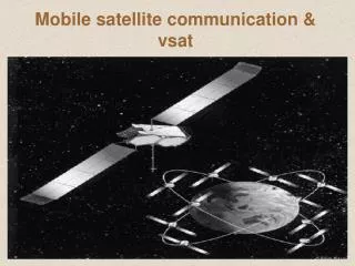
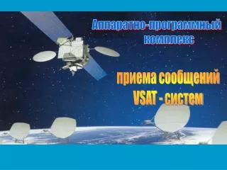
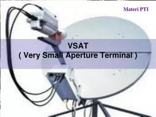
1. VSAT
2. VSAT � General Description A VSAT is an RF Modem/Terminal and antenna system which allows the user (Client) to communicate with the centralized Hub (Server) via a satellite link
Consists of the following Hardware:
Ku antenna, typically 0.75 to 1.20m
Outdoor Unit (ODU) containing the RF electronics
Inter-Facility Link (IFL) coaxial cables connecting the outdoor unit to the indoor unit
Indoor Unit (IDU) Terminal, containing a modulator, demodulator and baseband processing electronics Overview. The remote Skystar Advantage terminal consists of two modules: the Outdoor Unit (ODU) and the Indoor Unit (IDU). The end-user terminal is customer-owned and could consist of a Point of Sale (POS) device, Automatic Teller Machine (ATM), a file transfer-oriented machine (e.g., a PC), etc.
IDU. The IDU is located indoors at each remote site. It connects the user terminal ports to the Hub through the ODU and the satellite link. The IDU is designed for installation on the top of a bench or on a shelf of a 19� rack. Cables connecting End User terminals to the IDU ports should not be longer than 50 ft unless a line driver or short range modem is used.
A modern plastic enclosure is very easy to assemble/disassemble with a few snap-in parts and only 4 screws. The case has metal paint which meets EMI/RFI regulation approval. The IDU contains a burst mode modulator, continuous-mode demodulator, a MC68360 QUAD Integrated Communication Controller (QUICC) microprocessor with a clock that operates at 25 MHz or 33 MHz. The chassis accommodates three optional interface cards.
ODU. The ODU consists of the following components:
HPC - High power upconverter and amplifier for the transmit signal
LNB - Low Noise Block converter for the receiver signal
OMT - Orthomode transducer for connecting the up-converter transmitter and the LNB
VSAT Antenna
IFL. Interfacility Link. Two coaxial cables (one for the receive side, the other the transmit side) connecting the ODU to the IDU. Cable runs of 160 to 270 feet (depending upon cable type) are possible without line amplifiers; otherwise, runs of over 600 feet are possible with amplifiers.Overview. The remote Skystar Advantage terminal consists of two modules: the Outdoor Unit (ODU) and the Indoor Unit (IDU). The end-user terminal is customer-owned and could consist of a Point of Sale (POS) device, Automatic Teller Machine (ATM), a file transfer-oriented machine (e.g., a PC), etc.
IDU. The IDU is located indoors at each remote site. It connects the user terminal ports to the Hub through the ODU and the satellite link. The IDU is designed for installation on the top of a bench or on a shelf of a 19� rack. Cables connecting End User terminals to the IDU ports should not be longer than 50 ft unless a line driver or short range modem is used.
A modern plastic enclosure is very easy to assemble/disassemble with a few snap-in parts and only 4 screws. The case has metal paint which meets EMI/RFI regulation approval. The IDU contains a burst mode modulator, continuous-mode demodulator, a MC68360 QUAD Integrated Communication Controller (QUICC) microprocessor with a clock that operates at 25 MHz or 33 MHz. The chassis accommodates three optional interface cards.
ODU. The ODU consists of the following components:
HPC - High power upconverter and amplifier for the transmit signal
LNB - Low Noise Block converter for the receiver signal
OMT - Orthomode transducer for connecting the up-converter transmitter and the LNB
VSAT Antenna
IFL. Interfacility Link. Two coaxial cables (one for the receive side, the other the transmit side) connecting the ODU to the IDU. Cable runs of 160 to 270 feet (depending upon cable type) are possible without line amplifiers; otherwise, runs of over 600 feet are possible with amplifiers.
3. VSAT Basic Features
4. Front View of VSAT IDU Overview. The antenna is a standard component supplied to the system specifications. Its size depends upon many factors, among them the geographic location, the band used (C-Band or Ku-Band) and the inbound data rate. Typically the Ku-Band antenna size is 0.55 to 1.2 meters (1.8 to 4 feet), and the C-Band antenna size is 1.8 or 2.4 meters (6 or 8 feet).
The VSAT antenna includes a reflector, an offset feed horn, and mounting hardware. The standard reflector is a parabolic dish made of a glass fiber component.
Offset Angle. When the reflector aperture is perpendicular to the ground, the antenna is actually looking at the offset angle.Overview. The antenna is a standard component supplied to the system specifications. Its size depends upon many factors, among them the geographic location, the band used (C-Band or Ku-Band) and the inbound data rate. Typically the Ku-Band antenna size is 0.55 to 1.2 meters (1.8 to 4 feet), and the C-Band antenna size is 1.8 or 2.4 meters (6 or 8 feet).
The VSAT antenna includes a reflector, an offset feed horn, and mounting hardware. The standard reflector is a parabolic dish made of a glass fiber component.
Offset Angle. When the reflector aperture is perpendicular to the ground, the antenna is actually looking at the offset angle.
5. Front View of VSAT IDU LNB: Low Noise Block � Converts and amplifies the received signal from Ku-Band (~11.7 GHz) to L-Band (~950-1450 MHz).
SSPA: Solid State Power Amplifier/HPC � High Power Converter: Receives the L-Band signal from the VSAT IDU and amplifies and converts it to Ku-Band.
OMT: Orthomode Transducer: Acts as a filter, preventing the transmitted signal from leaking into the receive path of the LNB.
Feed Horn: The focal point of all accumulated signals from the reflector on the receive path and the point of origin of transmitting signal.
ODU Assembly and Installation.
After setting the antenna to the approximate azimuth and elevation angles, the ODU is assembled and attached to the antenna.
To assemble the ODU:
1. Attach the transmitter to the throughport of the OMT.
2. Attach the LNB to the H-Plane bend on the side port of the OMT.
3. Attach the feedhorn opposite the transmitter
4. After ODU assembly, place it on the mounting bracket of the antenna feed support arm, and secure it to the antenna support arm with the feed support top bracket.
Note: The ODU and LNB are delivered as separate units with the proper screws, nuts and O-rings. The OMT and feedhorn are part of the antenna kit.
LNB: Low Noise Block � Converts and amplifies the received signal from Ku-Band (~11.7 GHz) to L-Band (~950-1450 MHz).
SSPA: Solid State Power Amplifier/HPC � High Power Converter: Receives the L-Band signal from the VSAT IDU and amplifies and converts it to Ku-Band.
OMT: Orthomode Transducer: Acts as a filter, preventing the transmitted signal from leaking into the receive path of the LNB.
Feed Horn: The focal point of all accumulated signals from the reflector on the receive path and the point of origin of transmitting signal.
ODU Assembly and Installation.
After setting the antenna to the approximate azimuth and elevation angles, the ODU is assembled and attached to the antenna.
To assemble the ODU:
1. Attach the transmitter to the throughport of the OMT.
2. Attach the LNB to the H-Plane bend on the side port of the OMT.
3. Attach the feedhorn opposite the transmitter
4. After ODU assembly, place it on the mounting bracket of the antenna feed support arm, and secure it to the antenna support arm with the feed support top bracket.
Note: The ODU and LNB are delivered as separate units with the proper screws, nuts and O-rings. The OMT and feedhorn are part of the antenna kit.
7. DIP Switches. Switch 1 is to the left as you face the DIP switches from the rear of the IDU. The default position is for all switches to be OFF (down). Switches in use (and their purposes) are:
Switch 1. ON = Basic parameter configuration (Used during installation)
Switch 2. ON = Backup Satellite Parameters; OFF = Main Satellite Parameters
Switch 3. FLASH PROM Inhibit. ON = Boot from FLASH PROM is disabled
Switch 4. Not in Use. Should be set to OFF
Switch 5. ON = CW Test Mode; OFF for Normal Operation
Switch 6. Not in Use. Should be set to OFF
Switch 7. ON = Not in Use. Should be set to OFF
Switch 8. ON = RPP Simulator Mode ; OFF for Normal mode (To be used only by certified Technical Support Engineers)
Expansion Cards.
The three slots on the rear of the VSAT IDU permit using different types of expansion cards which all lead to a common bus. The IDU will sense which type of card is in which expansion slot.
DIP Switches. Switch 1 is to the left as you face the DIP switches from the rear of the IDU. The default position is for all switches to be OFF (down). Switches in use (and their purposes) are:
Switch 1. ON = Basic parameter configuration (Used during installation)
Switch 2. ON = Backup Satellite Parameters; OFF = Main Satellite Parameters
Switch 3. FLASH PROM Inhibit. ON = Boot from FLASH PROM is disabled
Switch 4. Not in Use. Should be set to OFF
Switch 5. ON = CW Test Mode; OFF for Normal Operation
Switch 6. Not in Use. Should be set to OFF
Switch 7. ON = Not in Use. Should be set to OFF
Switch 8. ON = RPP Simulator Mode ; OFF for Normal mode (To be used only by certified Technical Support Engineers)
Expansion Cards.
The three slots on the rear of the VSAT IDU permit using different types of expansion cards which all lead to a common bus. The IDU will sense which type of card is in which expansion slot.