Download
1 / 63
650 likes | 694 Views
Learn about load-line analysis, diode configurations, rectification processes, and clipper circuits. Understand key concepts and calculations for various diode applications.

E N D
Load-Line The applied load to the circuit will normally have an important impact on the point or region of operation of a device.
Load-Line Analysis The load line (the applied load)plots all possible combinations of diode current (ID) and voltage (VD) for a given circuit. The maximum ID equals E/R, and the maximum VD equals E. The point where the load line and the characteristic curve intersect is the Q-point, which identifies ID and VD for a particular diode in a given circuit. Quiescent point (abbreviated “Q-pt.”) to reflect its “still, unmoving” 3
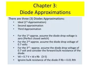
Series Diode Configurations Constants • Silicon Diode: VD = 0.7 V • Germanium Diode: VD = 0.3 V Analysis (for silicon) • VD = 0.7 V • VR = E – VD • ID = IR = IT = VR / R Forward Bias 4
Series Diode Configurations Diodes ideally behave as open circuits Analysis • VD = E • VR = 0 V • ID= 0 A Reverse Bias 5
EXAMPLE For the series diode determine (a) VDQ and IDQ. (b) VR.
EXAMPLE For the series diode configuration, determine VD, VR, and ID.
Since the applied voltage establishes a current in the clockwise direction to match the arrow of the symbol and the diode is in the “on” state, VD = 0.7 V
EXAMPLE • Determine Vo and ID for the series circuit
Example Determine the current I for the network:
Example: Determine the voltage Vo for the network
Half-Wave Rectification The diode only conducts when it is forward biased, therefore only half of the AC cycle passes through the diode to the output. The DC output voltage is 0.318Vm, where Vm = the peak AC voltage. 16
PIV (PRV) • Because the diode is only forward biased for one-half of the AC cycle, it is also reverse biased for one-half cycle. • It is important that the reverse breakdown voltage rating of the diode be high enough to withstand the peak, reverse-biasing AC voltage without entering the zener region. • PIV (or PRV) > Vm • PIV = Peak inverse voltage • PRV = Peak reverse voltage • Vm= Peak AC voltage 17
Full-Wave Rectification The rectification process can be improved by using a full-wave rectifier circuit. Full-wave rectification produces a greater DC output: • Half-wave: Vdc = 0.318Vm • Full-wave: Vdc = 0.636Vm 18
Full-Wave Rectification Bridge Rectifier • Four diodes are connected in a bridge configuration • VDC = 0.636Vm 19
Full-Wave Rectification • Center-Tapped Transformer Rectifier • Requires • Two diodes • Center-tapped transformer • VDC = 0.636Vm 20
Summary of Rectifier Circuits Vm= peak of the AC voltage. In the center tapped transformer rectifier circuit, the peak AC voltage is the transformer secondary voltage to the tap. 21
EXAMPLE Determine the output waveform for the following network and calculate the output dc level and the required PIV of each diode.
For the negative part of the input the roles of the diodes will be interchanged and vo will appear as
AND/OR GATES Positive logic OR gate.
AND/OR GATES positive logic AND gate
PIV For The Bridge Configuration The required PIV of each diode at the peak of the positive region of the input signal. For the indicated loop the maximum voltage across R is Vm and the PIV rating is defined by PIV Vm full-wave bridge rectifier
Diode Clippers Clipper is a variety of diode networks that have the ability to “clip” off a portion of the input signal without distorting the remaining part of the alternating waveform. 30
Series Clippers • The diode in a series clipper “clips” any voltage that does not forward bias it, such as half-wave rectifier series clippers
Biased Clippers Adding a DC source in series with the clipping diode changes the effective forward bias of the diode. 32
Example Determine the output waveform for the network
Example Determine the output waveform for the network
Parallel Clippers The diode (ideal) in a parallel clipper circuit “clips” any voltage that forward bias it. DC biasing can be added in series with the diode to change the clipping level. 37
Example Determine vo for the following network
Summary of Clipper Circuits more… 40
Clampers A diode and capacitor can be combined to “clamp” an AC signal to a specific DC level. 42
Biased Clamper Circuits The input signal can be any type of waveform such as sine, square, and triangle waves. The DC source lets you adjust the DC camping level. 43
In general, the following steps may be helpful when analyzing clamping networks: 1. Start the analysis of clamping networks by considering that part of the input signal that will forward bias the diode. 2. During the period that the diode is in the “on” state, assume that the capacitor will charge up instantaneously to a voltage level determined by the network. 3. Assume that during the period when the diode is in the “off” state the capacitor will hold on to its established voltage level. 4. Throughout the analysis maintain a continual awareness of the location and reference polarity for Vo to ensure that the proper levels for Vo are obtained. 5. Keep in mind the general rule that the total swing of the total output must match the swing of the input signal.
Example Determine vo for the following network for the input indicated.
The analysis will begin with the period t1 → t2 of the input signal since the diode is in its short-circuit state as recommended by comment 1. • For this interval the output is across R, but it is also directly across the 5-V battery the result is Vo 5 V for this interval. • Applying Kirchhoff’s voltage law around the input loop will result in • The capacitor will therefore charge up to 25 V, as stated in comment 2.
The open-circuit equivalent for the diode will remove the 5-V battery from having any effect on Vo, and applying Kirchhoff’s voltage law around the outside loop of the network will result in
Zener Diodes • When ViVZ • The Zener is on • Voltage across the Zener is VZ • Zener current: IZ= IR–IRL • The Zener Power: PZ = VZIZ • When Vi< VZ • The Zener is off • The Zener acts as an open circuit The Zener is a diode operated in reverse bias at the Zener Voltage (Vz). 50