Download
1 / 76
810 likes | 1.17k Views
1.2 - Digital Logic. Required : PM : Ch 2, pgs 5-25 Wiki : Finite State Machine Recommended : Code : Chs 10-16 Transistors and Faucets Gates , Tables, Expressions Combinational Logic Sequential Logic. Topics to Cover…. Logical and Arithmetic Operations Digital Logic Devices

E N D
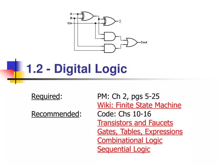
1.2 - Digital Logic Required: PM: Ch 2, pgs 5-25Wiki: Finite State Machine Recommended: Code: Chs 10-16Transistors and FaucetsGates, Tables, ExpressionsCombinational LogicSequential Logic
Topics to Cover… • Logical and Arithmetic Operations • Digital Logic Devices • The Transistor • Devices: Inverter, NAND, NOR, Drivers • Gates, Truth Tables, and Equations • Equations • De Morgan’s Law • Translations • Boolean Algebra • Combinational Logic devices • Decodes, Multiplexors, Adders, PLAs • Logical Completeness • Sequential Logic • Latches • Memory • Finite State Machine • Turing Machine Digital Logic
Logical Operations Logical Operations • NOT – Logical complement • OR, NOR – Logical disjunction • AND, NAND – Logical conjunction • XOR – Exclusive OR, A OR B, but not both 0 0 0 0 0 1 1 1 0 1 1 0 0 1 1 1 1 0 0 1 0 0 1 1 0 0 0 1 1 1 0 1 • Bitwise: 1010 1010 1010 OR0111AND0111XOR0111 1111 0010 1101 Digital Logic
Arithmetic Operations Arithmetic Operations • ADD – Summation, commutative and associative • SUB – Difference, neither commutative nor associative • NEG – Additive inverse 0 -1 1 -2 2 -3 3 -4 4 -5 5 + - -6 6 -7 7 -8 • Bitwise: 1010 (-6) 1010 (-6) ADD0111 (7)SUB0111 (7)NEG0111 (7) 0001 (1) 0011 (3) 1001 (-7) Digital Logic
Logical/Arithmetic Operations Quiz 1.2.1 • What are the results of the following logical operations? NOT 10112 10012 OR 10112 10012 NOR 10112 10012 AND 10112 10012 NAND 10112 10012 XOR 10112 • What are the results of the following 4-bit arithmetic operations (2’s complement)? NEG 10112 10012 ADD 10112 10012 SUB 10112 Digital Logic
The Transistor Semiconductors • A semiconductor is a material which has electrical conductivity properties of a metal (such as copper) and that of an insulator (such as glass). • Semiconductors are the foundation of modern solid state electronics. Digital Logic
The Transistor History of the Transistor • Around 1945, Bell Labs scientists discovered that silicon was comprised of two distinct regions differentiated by the way in which they favored current flow. • The area that favored positive current flow they named "p" and the area that favored negative current flow they named "n". • The transistor effect describes the change from a condition of conductivity (switched “on”, full current flow) to a condition of insulation (switched “off”, no current flow). Digital Logic
The Transistor Digital Logic Circuits • Computers = large number of simple structures • Intel 4004 = 2,300 transistors • Intel Pentium 4 = 42 million transistors • Intel Core 2 Duo = 291 million transistors • Intel i7 “Bloomfield” = 731 million transistors Digital Logic
2000’s 1990’s 1980’s 1970’s 1960’s 1950’s 1947 The Transistor Moore’s Law 2010’s Gordon E. Moore Moore’s Law: The number of transistors per area doubles every 1.5 - 2 years. Early 1900’s Digital Logic
The MOS Transistor A transistor acts like a switch Conducts current when "ON" No current flow when "OFF" N-type Transistor P-type Transistor gate gate current flow current flow Complementary The Transistor MOS = metal-oxide semiconductorCMOS = complementary MOS with both N and P transistors Digital Logic 12
CMOS Gates The Transistor 1 • Complementary pull-up / pull-down logic • pull-down is " ON" when pull-up is "OFF " • and vise versa. Pull-up Structure (P-Type) Output Complementary Pull-down Structure (N-Type) The “C” in CMOS Even in the digital world, "EVERYTHING IS ANALOG"! 0 Digital Logic 13
1 1 1 on off 0 1 in out 1 0 on off 0 0 0 This is a truth-table. It tells what the output will be for all combinations of the inputs. Symbols are abstractions! Digital Logic Devices The Inverter Digital Logic
The NOR Gate (NOT-OR) 1 1 1 a a 0 on on b b 0 on off NOR 1 0 off off on off 0 0 0 0 0 0 Digital Logic Devices Digital Logic 15
The OR Gate 1 a 1 b a OR OR b 0 0 0 Digital Logic Devices • How do you build an OR gate? Digital Logic 16
1 1 1 1 1 1 on off off off NAND 1 0 b 1 1 on on a 1 0 on off 0 0 0 Digital Logic Devices The NAND Gate (NOT-AND) Digital Logic
The AND Gate How do you build an AND gate? a AND AND b b a Digital Logic Devices Digital Logic 18
1 1 NAND b a 0 Digital Logic Devices Quiz 1.2.2 • Draw a logic circuit for a 3 input NAND gate (using N for N-type transistor and P for P-type transistor). Digital Logic
Drivers Bus Select Input Output Digital Logic Devices • Why can’t complementary logic connect to a bus? • A 0 and a 1 on the bus would let the magic smoke out! • Solution: Tri-state driver: All OFF 1 Any ON 0 +3.3v Pull-up Bus Digital Logic 20
Gates, Truth Tables, and Equations Digital Logic
The MOS Transistor A transistor acts like a switch Conducts current when "ON" No current flow when "OFF" N-type Transistor P-type Transistor gate gate current flow current flow Complementary Review MOS = metal-oxide semiconductorCMOS = complementary MOS with both N and P transistors Digital Logic 22
CMOS a NOT NAND b NOR b a in out 0 1 1 0 in sel out 0 0 - 0 1 0 1 0 - 1 1 - a b NOR 0 0 1 0 1 0 1 0 0 1 1 0 a b NAND 0 0 1 0 1 1 1 0 1 1 1 0 Review OUT Select Input Digital Logic 23
Equations Notation and Precedence • Logical operator notation (in order of precedence): • NOT, bar, circle, ~, ¬ • AND, *, , • OR, +, • Examples: y = NOT(s) AND a AND NOT(b) y = (~s a ~b) + (~s a b) ¬(xy) = ¬x ¬y Digital Logic
De Morgan’s Law NOR Symbols De Morgan’s Law To distribute the bar, change the operation. NAND Symbols Digital Logic 25
0 0 0 1 1 1 1 0 1 1 0 1 0 0 1 0 1 0 0 1 0 1 1 1 0 0 0 0 De Morgan’s Law De Morgan’s Proof Digital Logic
Translations You Should Know How to Translate These are three different ways of representing logical information LogicEquations You can convert any one of them to any other LogicGates TruthTables Digital Logic
s s a y a b b s a b y s y = (~s a ~b) + a b s a b Translations Gates Equations • Equations to Gates: y = NOT(s) AND a AND NOT(b) • Gates to Equations: (~s a b) + (s ~a b) + (s a b) Digital Logic 28
Quiz Quiz 1.2.3 • Translate the following equation to gates: AB + AC • Translate the following gates to an equation: Digital Logic
Equations Truth Tables Truth table to equations: s a b out 0 0 0 0 0 0 1 0 0 1 0 1 0 1 1 1 1 0 0 0 1 0 1 1 1 1 0 0 1 1 1 1 s a b out 0 0 0 0 0 0 1 0 0 1 0 1 0 1 1 1 1 0 0 0 1 0 1 1 1 1 0 0 1 1 1 1 • Equations to truth table: out = sa + sb Translations Each row of truth table is an AND gate Each output column is an OR gate Digital Logic 30
A B Cf 0 0 0 1 0 0 1 0 0 1 0 0 0 1 1 0 1 0 0 1 1 0 1 1 1 1 0 0 1 1 1 1 Quiz Quiz 1.2.4 • Translate the following truth table to an equation: • Translate the following equation to a truth table: f = ABC + ABC + ABC + ABC Digital Logic
Truth Tables Gates Truth table to Gates: ¬(¬A + S) = ¬¬A ¬S = A ¬S A S B C 0 0 0 0 0 0 1 0 0 1 0 0 0 1 1 1 1 0 0 1 1 0 1 1 1 1 0 0 1 1 1 1 • Gates to truth table: a a b out 0 0 0 0 1 1 1 0 1 1 1 0 b out Translations Each row of truth table is an AND gate Each output column is an OR gate Digital Logic 32
Quiz Quiz 1.2.5 • Translate the following truth table to gates: • Translate the following gates to a truth table: A B f Digital Logic
Boolean Algebra Manipulating Logic Expressions Laws (basic identities) of Boolean algebra. Digital Logic
Quiz 1.2.6 What is the logical equation and truth table for the following circuit? Quiz Digital Logic 35
W 2-to-4 Decoder X Y Z A W A B B DECODERSymbol X Y Z Circuits Decoders • Decode the input and signify its value by raising just one of its outputs. 1 if A,B = 00 1 if A,B = 01 A B W X Y Z 0 0 0 1 1 0 1 1 1 if A,B = 10 1 0 0 0 0 1 0 0 1 if A,B = 11 0 0 1 0 0 0 0 1 Digital Logic
A B S A B 0 1 S A B S C 0 X 0 0 1 X 0 1 X 0 1 0 X 1 1 1 C MULTIPLEXOR Symbol C Circuits Multiplexors • Connect one of its inputs to its output according to select signals • Useful for selecting one from a collection of data inputs. • Usually has 2n inputs and n select lines. Digital Logic
Circuits Adders • At each digit position add together the 2 operands and the carry-in b3 a3 b2 a2 b1 a1 b0 a0 c 0110 +0101 1011 Full Adder Full Adder Full Adder Full Adder ‘0’ c3 c2 c1 c0 s3 s2 s1 s0 • Just like longhand addition • except it’s in binary... Digital Logic
Circuits Full Adder Module Design a b c cyout sum 0 0 0 0 0 0 0 1 0 1 0 1 0 0 1 0 1 1 1 0 1 0 0 0 1 1 0 1 1 0 1 1 0 1 0 1 1 1 1 1 Digital Logic
? ? ? ? ? ? ? ? ? Outputs: ? ? ? ? ? ? ? ? ? ? ? ? ? ? ? Inputs: ? ? ? PLAs Programmable Logic Arrays • Programmable Logic Array (PLA) can be used to implement any logic function • Take truth table of any logic function • Convert into equation (any truth table can be expressed as set of “and” expressions “or”ed together) • PLA programmed by making/breaking wire connections Digital Logic
? ? Out1 = ABC + ABC + ABC ? ? ? ? ? ? ? Out1 Out2 A B C Out1 Out2 Out3 Out3 ? ? ? 0 0 0 0 1 1 ? ? ? 0 0 1 1 0 0 ? ? ? Outputs 0 1 0 0 1 0 ? ? ? ? ? ? 0 1 1 0 0 0 Inputs ? ? ? 1 0 0 1 0 0 A 1 0 1 0 1 0 1 1 0 0 0 0 B 1 1 1 1 0 1 C PLAs PLA Example Out2 = ABC + ABC + ABC Out3 = ABC + ABC Digital Logic
PLAs Quiz 1.2.7 • Implement a half adder using a PLA sum = abc+abc+abc+abc = a b c sum ? ? ? ? a ? ? ? ? ? ? ? ? b ? ? ? ? ? ? ? ? c ? ? ? ? ? ? ? ? Digital Logic
Logical Completeness • AND gate, INVERTER • OR can be replaced by an AND and three Inverters DeMorgan’s Theorem • OR gate, INVERTER • AND can be replaced by an OR and three Iinverters DeMorgan’s Theorem Logical Completeness • What is the minimum set of gate types needed to implement any logic function? • AND gate, OR gate, Inverter Digital Logic 44
Logical Completeness Logical Completeness • NAND • INVERTER • AND • OR NAND (by itself) is logically complete if you can implement an INVERTER, AND, and OR gate using only NAND gates. Digital Logic
Storage Elements Everything so far has been combinational logic the output is strictly a function of the current inputs Computing systems need storage elements for holding previously computed values for saving state Two types of locks: 4 1 8 4 30 25 5 Combinational – Success depends only on the values, not the order in which they are set. Sequential - Success depends on the sequence of values (e.g, R-13, L-22, R-3). 20 10 15 Sequential Logic Digital Logic 47
Bi-Stability = Key to Memory When there are 2 stable states - a bi-stable circuit RS Latch This is a stable state – it will sit like this forever This is also a stable state – it will sit like this forever 1 1 s s 0 1 q q 1 0 0 1 1 0 1 0 q q 1 1 r r Sequential Logic Digital Logic 48
s 1 1 s 1 q q 0 0 1 q q 1 1 r r This is a stable state – it will sit like this forever This is also a stable state – it will sit like this forever 0 1 1 1 0 1 1 0 0 1 1 0 0 1 1 1 1 0 1 1 Sequential Logic RS Latch – Bi-Stable Circuit Digital Logic
d s q WE D Q D-Latch we q r Latch Gated D Latch • Output q gets value from input d only when we is high • we stands for write enable, think of it as a load signal LATCH Symbol Symbols are abstractions! Digital Logic