Download
1 / 17
170 likes | 281 Views
MuCool RF Program. Muon Cooling R&D Alan Bross. MTA Hall. Fundamental Focus Of RF R&D. Study the limits on Accelerating Gradient in NCRF cavities in magnetic field It has been proposed that the behavior of RF systems in general can be accurately described (predicted) by universal curves

E N D
MuCool RF Program Muon Cooling R&D Alan Bross Alan Bross MICE CM - Daresbury June 7, 2008
MTA Hall Alan Bross MICE CM - Daresbury June 7, 2008
Fundamental Focus Of RF R&D • Study the limits on Accelerating Gradient in NCRF cavities in magnetic field • It has been proposed that the behavior of RF systems in general can be accurately described (predicted) by universal curves • Electric Tensile Stresses are important in RF Breakdown events • This applies to all accelerating structures Alan Bross MICE CM - Daresbury June 7, 2008
Detailed Modeling Code Now Available Must define experiments to vet this code Alan Bross MICE CM - Daresbury June 7, 2008
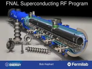
NCRF Model Extended to SCRF • We have extended this model to SCRF and high frequency problems. • We are working with the Argonne Materials Science Division to develop: • A materials science program to understand chemical, morphology and electronic properties of rf SCRF and NC materials • Cavity tests to determine optimum procedures and performance. • This program is underway and, using Argonne internal funding, and has produced important results: • We have developed a model of High Field Q-Slope based on magnetic oxides, that seems to explain SCRF cavity data. • We have developed a new procedure to produce niobium surfaces without complex oxides. • We are beginning a program of cavity testing with JLab. • Using Atomic Layer Deposition and other newly developed materials science techniques we can synthesize and analyze surfaces with unprecedented precision. • Limits maximum gradient Alan Bross MICE CM - Daresbury June 7, 2008
Extension To SCRF • We are extending our experimental program to explore the ultimate gradient limits of “perfect” surfaces, which have the properties that (ATOMIC LAYER DEPOSITION): • They are smooth at the nanometer level, so local fields (~1/r) cannot be high enough to produce field emission or breakdown events • They are layered, with thin superconducting layers that are expected to be resistant to B field quenches. • They are homogeneous, so local “hot spots” should not exist. • They can be applied “in-situ” so they are not subject to assembly defects. • They allow almost complete freedom to choose substrate for conductivity, rigidity, etc. to avoid thermal, Lorentz and microphonics effects. • We expect we should be able to address known failure modes and produce structures that reach significantly higher gradients in both normal and superconducting systems. Alan Bross MICE CM - Daresbury June 7, 2008
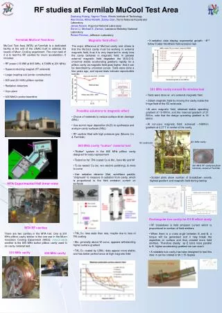
The Basic Problem – B Field Effect805 MHz Studies • Data seem to follow universal curve • Max stable gradient degrades quickly with B field • Remeasured • Same results >2X Reduction @ required field Gradient in MV/m Peak Magnetic Field in T at the Window Alan Bross MICE CM - Daresbury June 7, 2008
805 MHz Imaging Alan Bross MICE CM - Daresbury June 7, 2008
Next 805 MHz study - Buttons • Button test • Evaluate various materials and coatings • Quick Change over Alan Bross MICE CM - Daresbury June 7, 2008
Button test results: 2007/8 • TiN_Cu data: • less stable than rest, maybe due to loss of TiN coating • Modata: • generally above W data • Mo appears to withstand higher surface field than W –LBNL TiN_Cu #2 • 2008 tests: • more careful conditioning to avoid coating damage • New TiN_Cu button (LBNL #2): • data appear more stable than FNAL-coatedTiN_Cu • better performance at high magnetic field Alan Bross MICE CM - Daresbury June 7, 2008
805 Cavity Damage Alan Bross MICE CM - Daresbury June 7, 2008
805 – What Next? • These observations were unexpected • 805 Program on hold until we fully evaluate condition of cavity and decide how to proceed Alan Bross MICE CM - Daresbury June 7, 2008
RF R&D – 201 MHz Cavity Design • The 201 MHz Cavity – 19 MV/m Gradient Achieved (Design – 16MV/m) • In low (few hundred G) B field. Still no breakdown. Limited by available power Alan Bross MICE CM - Daresbury June 7, 2008
201 MHz Cavity Operation in B Field • Initial 201 MHz operation in B Field • Limited to few hundred Gauss • Using Fringe Field of 4T magnet (in blue) 5T – Solenoid Mode Alan Bross MICE CM - Daresbury June 7, 2008
201 in Position • We have now moved 201 as close as possible to 5T solenoid • Can obtain »1.5T on near window of 201 Alan Bross MICE CM - Daresbury June 7, 2008
Radiation at 0.5-T Field Radiation data compared with a fitting with to gradient to ~ 14th power 0.5-T B field to the nearest Be window Radiation (mRem/hr) Represent Chipmonk #1, #2 and #3, respectively Cavity Gradient (MV/m) Alan Bross MICE CM - Daresbury June 7, 2008
MuCool Plans for the Coming Year • 805 MHz RF studies – Buttons (with and without B field) • Materials tests • Surface treatment (HP Wash + EP (from UK), ALD (Argonne) • E X B study • 201 MHz RF • Continue B field studies • Working with Linac Group to improve operational efficiency • Begin thermal and mechanical tests on HIP LiH absorber prototypes • Complete MTA cryo infrastructure installation and commission system • Commission Beam Line • First tests with Beam Complete by January 09 (MCTF) • Test of Muons Inc. HP H2 RF test cell with beam Alan Bross MICE CM - Daresbury June 7, 2008