Download
1 / 18
180 likes | 306 Views
Simulations of Neutralized Drift Compression. D. R. Welch, D. V. Rose Mission Research Corporation Albuquerque, NM 87110 S. S. Yu Lawrence Berkeley National Laboratory Berkeley, CA C. L. Olson Sandia National Laboratories Albuquerque, NM Presented at the ARIES Project meeting

E N D
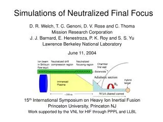
Simulations of Neutralized Drift Compression D. R. Welch, D. V. Rose Mission Research Corporation Albuquerque, NM 87110 S. S. Yu Lawrence Berkeley National Laboratory Berkeley, CA C. L. Olson Sandia National Laboratories Albuquerque, NM Presented at the ARIES Project meeting At Georgia Tech, September 4, 2003
Focusing ion beams Chamber first wall Plasma drift region 10 cm Adiabatic section Hybrid target B 10 m 50 kA channel current Beams drift, combine and possibly compress in plasma drift region • 10-80 beams per side • Combined beams must focus to a 1-cm spot at the adiabatic discharge channel to couple to hybrid target (0.5-cm radiator - D. A. Callahan, M. C. Herrmann, M. Tabak, Laser and Particle Beams, 20, 405-410 (2002). ) 1013-1015 cm-3 Goal is determine transport characteristics and stability regimes of compressing/combining beams in neutralizing plasma
Topics • Plasma-neutralized drift transport in a solenoidal field for a driver beam • Search for optimal transport conditions • Extreme neutralized drift compression (NDC) with IBX parameters for HEDP applications • Compress in neutralizing volumetric plasma • Need to compress ½ J beam to 0.2 ns (to avoid target disassembly) and 1 mm radius for 1011 J/m3 energy density
What solendoid/plasma conditions yield best beam transport? • For near term laboratory experiments, residual net currents are not a problem – np >> nb is sufficient • For a driver, we need to worry about minimizing both electrostatic and magnetic self fields • Examine problem with simulations of driver beam injected into preformed plasma with solenoidal field (no compression)
6-7 kA net currents calculated for beam without applied Bz • 150 kA, 200 MeV Ne+ beam, normal injection with 10-cm sharp-edged radius, 15-cm tube filled with 1012 cm-3 plasma – finer resolution, more 6x more particles • 6-kA net current predicted by laminar flow theory Net current with radius R at 80 ns Beam density at 80 ns
Net currents decrease with increasing Bz and skin depth to cyclotron radius* • 150 kA, 200 MeV Ne+ beam, normal injection with 10-cm sharp-edged radius • Net current is 1.5 kA for 2 kG fields, 0.7 kA for 8 kG • Here skin depth to cyclotron radius,ce / p = 4.33, 18 Net current with radius R at 60 ns for 2 kG Bz Net current with radius R at 60 ns for 8 kG Bz * Consistent with model of I. Kagonovich, PPPL
Net Current scaling with Bz • Averaged over 5 cm about z=150 cm at 60 ns
Matched rotating ion beam case • 2.7 kA, 200 MeV, 10 cm Ne+ ion beam (cold) • Ne rotation matched with 5 T solenoidal field • Transport for 2 meters in 15-cm drift tube with electron emission from outer wall • 2x10¹⁰- 2x1013 cm-3 uniform 3-eV plasma density • LSP explicit simulation – electron cyclotron and plasma frequencies resolved • Beam density nb = 1.3x1010 cm-3 • 4 simulations with c = 8.8x10¹¹ s-1 • p = 0.01, 0.03, 0.1, 0.3 c • np = 1.5, 15, 150, 1500 nb
Beam transport improves with plasma density as long as c > p t=40 ns np = 1.5 nb np = 150 nb np = 15 nb np = 1500 nb
ES potential drops with plasma density 40 ns np = 1.5 nb np = 150 nb np = 1500 nb np = 15 nb Potential drops to noise level for 1500 density ratio
Transport is most ballistic with large plasma density and applied solenoidal field • np >> nb and c > bp produces best transport • Residual electrostatic potential small for np >> nb • Azimuthal self magnetic field small for c > p* * Also consistent with model of I. Kagonovich, PPPL
IBX Neutralized Drift Compression • 6 MeV, 0.35 A K+ beam (.32 J, 10-4 perveance) • 1 pi-mm-mrad emittance • Beam profile • uniform 3-cm outer radius with 50 ns rise and fall in density ( 1.4x108 cm-3 density) • Velocity tilt 0.017-0.019c in 200 ns pulse • Focus at z = 980 cm • 10-m drift length, 20-m focal length • No beam energy error at injection • Plasma density initialization • Increasing 109 – 1.75x1010 cm-3 • 2D Lsp simulations • Electromagnetic, explicit particles • Outer wall SCL electron emission • 2.5-mm, < .1 ns resolution • Double precision Plasma density Requires factor of 1000 axial compression No guide solenoidal magnetic field
Ballistic beam compresses to 300 Amps – 1000 compression • Constant radius beam, 50-ns rise/fall, 980-cm compression length • Limited by resolution z=980 cm z=940 cm z=900 cm z=500 cm z=100 cm Longitudinal phase space still cold just before focus
z=980 cm z=940 cm z=900 cm z=500 cm z=100 cm Full Lsp simulation calculates compressed to 200 A • Including self EM fields, plasma effects Total energy Energy error Small numerical energy error
No significant growth in emittance • Current loss to wall 0.04% z=980 cm z=940 cm z=500 cm z=900 cm z=10 cm probes at different axial positions Therefore, focusing still possible after compression.
Small growth in longitudinal energy spread • Constant radius profile, increasing plasma density • Wiggles in energy seen beyond 1800 ns - 2 stream or numerical?
Electron oscillation evident • Weak 2-stream instability? • wavelength consistent = 2 (c p)-1/2 6 mm • Does beam compression reduce instability?
Simulations show robust drift compression in a neutralizing plasma • IBX parameters were simulated with a velocity tilt to compress to 0 pulse length in 980 cm • Beam compresses by nearly 600 in full sim • No calculated transverse emittance growth • Beam can still be focused radially! • Weak beam-electron two-stream instability • Simulations of NDC with NTX parameters are underway Reasonable beam compression ratios limited only by accuracy of velocity tilt!