Download
1 / 14
150 likes | 298 Views
A Short Introduction to DSP Microprocessor Architecture. R.C. Maher ECEN4002/5002 DSP Laboratory Spring 2003. Memory. Address. CPU/ALU. Data. What makes a DSP chip a DSP?.

E N D
A Short Introduction to DSP Microprocessor Architecture R.C. Maher ECEN4002/5002 DSP Laboratory Spring 2003 DSP Lab Intro R. C. Maher
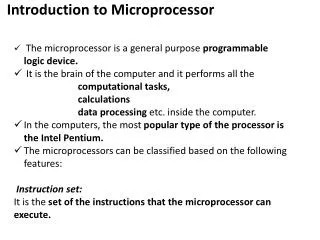
Memory Address CPU/ALU Data What makes a DSP chip a DSP? • Conventional microprocessors use the Von Neumann architecture: program and data all in a single memory. Address and data buses are shared between instruction and data fetches. DSP Lab Intro R. C. Maher
Von Neumann architecture is inexpensive, simple, and effective, BUT there are performance problems: • Von Neumann “bottleneck”: fetch for next instruction collides with data fetch/store • Buses may be idle during instruction decode • DSP algorithms often have “multiply-accumulate” requirements: coef[n] * data[n], where two operands must be fetched • Most DSP chips use Harvard architecture: separate memory space(s) for program and data DSP Lab Intro R. C. Maher
Harvard Architecture Program Memory P Address CPU/ALU Instr. D1 Address D1 Data D2 Data D2 Address Data Memory #1 Data Memory #2 DSP Lab Intro R. C. Maher
DSP Architectural Features • ALU typically centered around Multiply-Accumulate (MAC) structure with large accumulator • Digital filters require accumulated sum-of-products • Multiple address generators to handle separate memory spaces • Address units handle modulo buffer arithmetic DSP Lab Intro R. C. Maher
-20 2-1 2-2 2-3 2-(n-1) DSP Data Representation • Numerical values represented as binary fractions: -1.0 value < 1.0 Radix point Sign bit DSP Lab Intro R. C. Maher
Why a fractional representation? • The product of two fractional numbers is also a fractional number • Normalized representation is convenient • Coefficients from digital filter designs are typically already in fractional form DSP Lab Intro R. C. Maher
Input Register Input Register Mult Guard Accum High Accum Low DSP Architecture: Accumulator • Accumulator register holds intermediate results (n-bit number x n-bit number yields 2n-1 bit number) • Accumulator typically has extra “guard bits” or “extension register” for overflow DSP Lab Intro R. C. Maher
Accumulator Example Sign bit 28 … 21 20 2-1 … 2-23 2-24 … 2-47 … … … Guard (8 bits) Accum High (24 bits) Accum Low (24 bits) Radix point Motorola 56xxx has two 56-bit accumulators (48-bit result with 8 guard bits) DSP Lab Intro R. C. Maher
Digital Filter Example • Simple FIR filter is given by • Current output is sum of product of coefficients and past input values. DSP Lab Intro R. C. Maher
+ Filter example (cont.) x[n] y[n] b0 Z-1 x[n-1] Z-1 b1 x[n-2] b2 Z-1 x[n-3] b3 DSP Lab Intro R. C. Maher
Filter example (cont.) • Procedure: • Clear accumulator • Fetch coefficient and data • MAC • Repeat fetch & MAC until done DSP Lab Intro R. C. Maher
DSP Support for Parallel Moves • Need to fetch next coefficient and next stored value at each step in the filter • DSPs generally support a parallel move or fetch operation while MAC is computed • This design avoids idle ALU and data buses Ex: mac x0,y0,a x:(r0)+,x0 y:(r4)+,y0 DSP Lab Intro R. C. Maher
Summary • DSP chips use the Harvard architecture: separate program and data memory spaces • ALU is centered around the multiply-accumulate (MAC) function • DSPs typically use a fractional number representation • Address computation generally supports modulo buffer address arithmetic • DSPs avoid idle cycles by allowing parallel actions DSP Lab Intro R. C. Maher