Download
1 / 45
990 likes | 3.68k Views
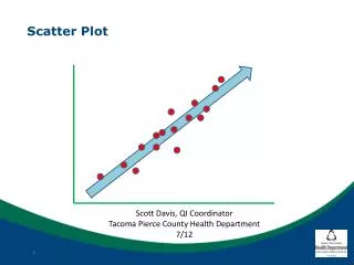
Dose Distribution and Scatter Analysis. Phantoms Depth Dose Distribution Percentage Depth Dose Tissue-Air Ratio Scatter-Air Ratio. Phantoms.

E N D
Dose Distribution and Scatter Analysis • Phantoms • Depth Dose Distribution • Percentage Depth Dose • Tissue-Air Ratio • Scatter-Air Ratio
Phantoms • Water phantom: closely approximates the radiation absorption and scattering properties of muscle and other soft tissues; universally available with reproducible
PHANTOMS • Basic dose distribution data are usually measured in awater phantom, which closely approximates the radiation absorption and scattering properties of muscle and other soft tissue • Another reason for the choice of water as a phantom material is that it isuniversally available with reproducible radiation properties.
PHANTOMS • Solid dry phantoms • tissue or water equivalent, it must have the same • effective atomic number • number of electrons per gram • mass density • For megavoltage photon beams in the clinical range, the necessary condition for water equivalence • same electron density (number of electrons per cubic centimeter) Compton effect is the main interaction
Alderson Rando Phantom • anthropomorphic phantom • Frequently used for clinical dosimetry • Incorporates materials to simulate various body tissues, muscle, bone, lung, and air cavities
RANDO phantom CT slice through lung Head with TLD holes
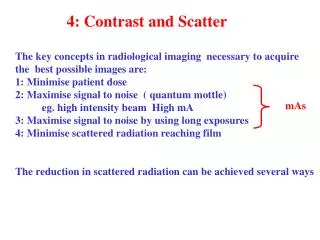
Depth Dose Distribution • The absorbed dose in the patient varies with depth • The variation depends on depth, field size, distance from source, beam energy and beam collimation • Percentage depth dose, tissue-air ratios, tissue-phantom ratios and tissue-maximum ratios---measurements made in water phantoms using small ionization chambers
collimator surface d0 D d0 d D d phantom Percentage Depth Dose • Absorbed dose at any depth: d • Absorbed dose at a fixed reference depth: d0
PERCENTAGE DEPTH DOSE • For orthovoltage (up to about 400 kVp) and lower-energy x-rays, the reference depth is usually the surface (do = 0). • For higher energies, the reference depth is taken at the position of the peak absorbed dose (do = dm).
collimator surface dm D max d D d phantom Percentage Depth Dose • For higher energies, the reference depth is at the peak absorbed dose ( d 0= d m) • D max : maximumdose, the dose maximum,the given dose
Percentage Depth Dose • (a)Dependence on beam quality and depth • (b)Effect of field size and shape • (c)Dependence on SSD
Percentage Depth Dose(a)Dependence on beam quality and depth • Kerma— (1) kinetic energy released per mass in the medium; (2) the energy transferred from photons to directly ionizing electron; (3) maximum at the surface and decreases with depth due to decreased in the photon energy fluence; (4) the production of electrons also decreases with depth
Percentage Depth Dose(a)Dependence on beam quality and depth • Absorbed dose: • (1) depends on the electron fluence; • (2) high-speed electrons are ejected from the surface and subsequent layers; • (3) theses electrons deposit their energy a significant distance away from their site of origin
Fig. 9.3 central axis depth dose distribution for different quality photon beams
Percentage Depth Dose(b)Effect of field size and shape • Geometrical field size: the projection, on a plane perpendicular to the beam axis, of the distal end of the collimator as seen from the front center of the source • Dosimetric ( Physical ) field size: the distance intercepted by a given isodose curve (usually 50% isodose ) on a plane perpendicular to the beam axis
PDD - Effect of Field Size and Shape • Field size • Geometrical • Dosimetrical or physical SAD FS
Scatter dose Dmax Dd Percentage Depth Dose(b)Effect of field size and shape • As the field size is increased, the contribution of the scattered radiation to the absorbed dose increases • This increase in scattered dose is greater at larger depths than at the depth of D max , the percent depth dose increases with increasing field size
Percentage Depth Dose(b)Effect of field size and shape • Depends on beam quality • The scattering probability or cross-section decreases with energy increase and the higher-energy photons are scattered more predominantly in the forward direction, the field size dependence of PDD is less pronounced for the higher-energy than for the lower-energy beams
Percentage Depth Dose(b)Effect of field size and shape • PDD data for radiotherapy beams are usually tabulated for square fields • In clinical practice require rectangular and irregularly shaped fields • A system of equating square fields to different field shapes is required: equivalent square • Quick calculation of the equivalent
square field rectangular field c A B c A x B c = 2 x A + B
a b Percentage Depth Dose(b)Effect of field size and shape • Quick calculation of the equivalent field parameters: for rectangular fields • For square fields, since a = b, • the side of an equivalent square of a rectangular field is
a b Percentage Depth Dose(3)--(b)Effect of field size and shape • Equivalent circle has the same area as the equivalent square r
Percentage Depth Dose(c) dependence on SSD • Photon fluence emitted by a point source of radiation varies inversely as a square of the distance from the source • The actual dose rate at a point decreases with increase in distance from the source, the percent depth dose, which is a relative dose, increases with SSD • Mayneord F factor
Dose rate in free space from a point source varies inversely as the square of the distance. (IVSL) scattering material in the beam may cause deviation from the inverse square law. PDD increases with SSD IVSL SSD’ SSD dm dm d d PDD - Dependence on Source-Surface Distance
Percentage Depth Dose (c) dependence on SSD F1+dm F2+dm F1+d F2+d Fig. 9.5 Plot of relative dose rate as inverse square law function of distance from a point source. Reference distance = 80 cm
f1 f2 r dm r d dm d
f1 r dm d dm d f2 r • PDD increases with SSD • the Mayneord F Factor ( without considering changes in scattering )
PDD - Dependence on Source-Surface Distance • PDD increases with SSD
Example The PDD for a 15×15 field size, 10-cm depth, and 80-cm SSD is 58.4-Gy (C0-60 Beam). Find the PDD for the same field size and depth for a 100-cm SSD Assuming dm=0.5-cm for (C0-60 Gamma Rays). F=1.043 P= 58.4*1.043=60.9
Percentage Depth Dose(c) dependence on SSD • Under extreme conditions such as lower energy, large field (the proportion of scattered radiation is relatively greater), large depth, and large SSD, the Mayneord F factor is significant errors • In general, the Mayneord F factor overestimates the increase in PDD with increase in SSD
PDD - Dependence on Source-Surface Distance • PDD increases with SSD • the Mayneord F Factor • works reasonably well for small fields since the scattering is minimal under these conditions. • However, the method can give rise to significant errors under extreme conditions such aslower energy, large field, large depth, and large SSD change.
Tissue-Air ratio • The ratio of the dose ( D d) at a given point in the phantom to the dose in free space ( D f s ) • TAR depends on depth d and field size rd at the depth: (BSF) Equilibrium mass phantom d rd rd Dd D f s
Tissue-Air ratio( a ) Effect of Distance • Independent of the distance from the source • The TAR represents modification of the dose at a point owing only to attenuation and scattering of the beam in the phantom compared with the dose at the same point in the miniphantom ( or equilibrium phantom ) placed in free air
Tissue-Air ratio( b ) Variation with energy, depth, and field size • For the megavoltage beams, the TAR builds up to a maximum at the d m and then decreases with depth • As the field size is increased, the scattered component of the dose increases and the variation of TAR with depth becomes more complex
Tissue-Air ratio( b ) Variation with energy, depth, and field size: BSF • Backscatter factor (BSF) depends only on the beam quality and field size • Above 8 MV, the scatter at the depth of Dmax becomes negligibly small and the BSF approaches its minimum value of unity
The meaning of Backscatter factor • For example, BSF for a 10x10 cm field for 60Co is 1.036 means that D max will be 3.6% higher than the dose in free space • This increase in dose is the result of radiation scatter reaching the point of D max from the overlying and underlying tissues
Tissue-Air ratio ( c ) relationship between TAR and PDD
Tissue-Air ratio ( c ) relationship between TAR and PDD-- Conversion of PDD from one SSD to another : The TAR method Burns’s equation:
Tissue-Air ratio ( d ) calculation of dose in rotation therapy d=16.6
Equilibrium mass phantom d rd rd Dd D f s Scatter-Air Ratio(SAR) • Calculating scattered dose in the medium • The ratio of the scattered dose at a given point in the phantom to the dose in free space at the same point • TAR(d,0): the primary component of the beam
Average tissue-air ratio Average scatter-air ratio TAR ( 0 ) = tissue-air ratio for 0 x 0 field Scatter-Air Ratio--Dose calculation in irregular fields: Clarkson’s Method Based on the principle that the scattered component of the depth dose can be calculated separately from the primary component