Download
1 / 67
690 likes | 740 Views
Detailed insights into CLIC Workshop operations and events, covering equipment installation, beam recombination, calibration, and validation |

E N D
CTF3 Commissioning and Operation Simona Bettoni, Caterina Biscari, Roberto Corsini, Anne Dabrowski, Steffen Doebert, Andrea Ghigo,Seyd Hamed Shaker,Piotr Skowroński, Frank Tecker CLICWorkshop CERN 15October 2008 CLIC Workshop
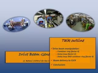
recombinationx 4 recombination x 2 bunch lengthcontrol bunchcompression fully loadedacceleration structures12 GHz phase-coding PETSon-off Decelerationstability two-beamacceleration structures 30 GHz CTF3 base line programme CTF3 – R&D Issues - where CLIC Workshop
CLIC Test Facility 3 TL1 & CRM commissioned fall 2006 Delay Loop: commissioned with beam 2005-2006 Linac: commissioned with beam 2003 - 2004 CRM TL1 DL CR TL2 CLEX CR commissioningsince 2007 TL2 and TBTS commissioning started August 2008 3 CLIC Workshop
Main Points of 2006 • Delay Loop Commissioned • 7A after DL • 1400 ns pulse length • TL1 and CR injectionCommissioned • 3.2A in TL1, 3A in CRM • RF injection to CR 2 1 3 CLIC Workshop
Main Points of 2007TL1 and CR • Transfer Line 1 relatively quickly commissioned • No major problems with establishing injection to CR • Long and painful CR commissioning being finished only now • Fast Vertical Instability caused by the deflectors • Bad cabling of quadrupoles • Wrongly calibrated BPMs • Unstable gun • Inaccurate model of the ring current Vpos Hpos 5 CLIC Workshop
Main Points of 2007CR results • Besides all the problems • We have managed to recombine the train factor 4 • OK, almost 4, but the principle was shown to be valid • Perform the optics studies which enabled gradualdebugging and validation of the machine model CLIC Workshop
Operations CLIC Workshop • The machine is operated in two modes • PETS beam for 30GHz structures tests • From Friday to Monday morning • Setup is done by CTF3 team • Night and weekend supervision from CCC by PS operators • Commissioning beam • From Monday to Thursday • Two overlapping shifts (volontary), • From 8AM to 4PM • From 2PM to 8PM • PhD students tend to extend it voluntarily till 3AM
Schedule 2008 v3 30 GHz DL & CR 30GHz only RUN 1 DL, CR, TL2 TBTS Installation:TL2, CALIFES, TBTS, new deflectors Today Linac only RUN 2 Linac, Ring area, (CLEX) PETS in TBTS Today CALIFES Installation: tail clipper RUN 3 CLIC Workshop
2008 program – Run 1 • Find and repair the problem with the gun • Linac • establish stable & documented working point • stability studies • diagnostic consolidation • Delay Loop • Beam optics measurements • Re-establish recombinations • Finish the commissioning of CR • Perform set of optics measurements • Validate the machine model • tune and bfunction dependence of vertical instability • Test new devices and techniques • EuroTeV BPMs • Bunch length measurement with RF pickup • Transient compensation • Dispersion Free Steering and other automatic algorithms CLIC Workshop
2008 program – Installations 1 • Technical break in summer for • Complete TL2 installation • Install new deflectors (!) • Complete CLEX installations • When the dump after CR was removed to make place for TL2 personnel was not allowed to enter CLEX when the beam was in DL or CR (and vice versa) CLIC Workshop
2008 program – Run 2 • Run 2 • Commission the new RF deflectors • Re-setup beam recombination in CR • Full recombination with DL and CR (factor 8) • Commissioning of • TL2 • TBTS (no PETS) • First trial for CALIFES • Installations 2 (beginning of Oct) • Tail clipper • Run 3 • Commissioning of • CALIFES • TBTS (wtih PETS) • Coherent Diffraction Radiation tests CLIC Workshop
Machine Setup on one slide • Machine setup is based on quad scans • Beam is set-up to the screen on girder 10 • Phases of acc-structures up to girder 10 are adjusted to get full loading • Twiss parameters are measured and whole linac is rematched • Phase adjustment for the rest of the structures • Energy profile is measured at girder 10 and elsewhere is calculated • Another quad scan is made at CTS • TL1 and is matched to the CR closed solution at this given energy • If something changes at given point, we must redo the setup from there CRM TL1 DL CR TL2 CLEX
Beam recombination in CR is made with time variable bump injection line septum 1st deflector 2nd deflector local inner orbits RF deflector field lo CR Injection (b) (a) 13 CLIC Workshop 15 Oct 2008
Long circulating CR beam • Many measurements require long ciruclating beam in CR • Tune • Closed orbit correction • Closed orbit length measurement • The beam is injected to the ring RF deflectors • The klystron timing is adjusted so the RF pulse ends when the last bunch of the train leaves the deflector • Since those are travelling wave cavities with short filling time the RF is gone before the first beam of the train comes back to the deflector • This way beam makes several hundreds turns before it irradiates too much energy thru synchrotron radiation to be fitted in the acceptance
Unstable gun Unstable Stable CLIC Workshop • Already since the first run of 2007 we observe large beam jitter that originates from the gun instability • The current is slightly different from shot to shot • Since we operate in the fully loaded mode • phases are adjusted so all the RF energy is transferred to the beam bunches with different current are accelerated differently • It leads position jitter in the dispersive regions • What makes the setup and measurements very hard!
Unstable gun (cont.) CLIC Workshop • Finding the problem was difficult and tedious • the system operates on high voltage (130-150kV) and hence specialized knowledge and equipment is needed for investigations • On top of that the device is constructed by LAL and the designer is retired • It was finally found that the high voltage power converter produces chainsaw-like signal • however according to the manufacturer the device itself was OK • After inspection in-situ one of resistors was found cracked • connecting capacitor bank to the ground • at low voltage the resistance was 0, but when 150kV applied than it was conducting thru arcing • And later another resistor found cracked • between capacitor bank and the high voltage deck • Since than (end of September 2008) the gun behaves OK • However, we are not certain that it was the core of the problem and it is going to come back at some point
Optics Studies andModel Validation • The main reason for extensive optics measurements is verification that the model predicted optics well agrees with the measured one, and if they don’t • Machine was not build according to the specification • There is a bug in the model • One can not back-hand the setup with the model calculations • We performed the following optics measurements • Dispersion • Response Matrix • Tunes • Combiner Ring Length • Bunch length • Quadrupole current to K1 coefficient CLIC Workshop
Response Matrix • Register the orbit position in all BPMs • Change one of the correctors • Look into orbit position change (difference) • Compare with the model predicted change • If they do not agree, the model does not describe the machine correctly • It is relatively easy to localize the element that is badly modeled • Between the element the discrepancy occurs first and the previous one or two • Even if there are more errors we still can find them • If the kick is applied after the first error the pattern should agree • The measurements are automatized with a MatLAB script CLIC Workshop 21Jan 2008
The Response Matrix Study • Already during 2007 runs response matrix study allowed to find few problems with the CR model • Current to gradient coefficient for J type magnets (5%) • Wiggler focusing • Some discrepancies were still present • They were not localized in a precise location • Large statistical uncertainties originating in the gun instability did not allow to find the subtle problems quickly CLIC Workshop
High precision Response Matrix measurement • For each corrector we performed larger set of measurements with different values of the kick, starting with very small values • Response should be linear with the kick • Points that do not lay on the line defined by the majority of the (low amplitude) points are not concidered • Fit to the remaining points defines the matrix element much more precisely. • The is way we reduce uncertainty of the measurement CLIC Workshop
Tunes • We measure tunes doing FFT of a pickup analog signal using a scope • More about it in the next presentation CLIC Workshop
Dispersion • Dispersion is measured with „line scaling” technique • All magnetic elements are scaled by some small factor • This makes the beam energy mismatched to the line setup • Easier for us comparing to energy change • Allows to measure dispersion section-wise, starting at any given element • More about it in the next talk by Simona CR CLIC Workshop
Measurement of the ring length BPR: RF Phase Monitor Gives sum of the beam induced signal and internal frequency (3GHz) If beam has also 3GHz it measures phase offset between the two signals 4th turn 3rd turn 1st turn 2nd turn Simulated signal Combination factor 4 Combination factor 4 with + 5 error CLIC Workshop
BPR measurement • Short pulse for many turns • FFT of the BPR signal gives the ring length • frev gives total ring length LR= (N – 1/CF) lRF • Df gives fractional part of ring length 1/CF lRF B A Df = (A - B) / 2 BPR signal Suppressed revolution frequency fREV =(A + B) / 2 FFT CLIC Workshop
A fREV =(A + B) / 2 Theoretical fREV B BPR measurement: frev Do the measurement for different values of the wiggler current Theoretical fREV fREV =(A + B) / 2 Measured LR = c b / fREV LR = (849 - 0.225) lRF Theoretical LR = (848 - 0.225) lRF CLIC Workshop
BPR measurement: Df expected measured CF 5, - 1/5 lRF About 1.5 mm Expected ring length for nominal wiggler current Measured Lfrac = - 1/CF lRF CF 4, - 1/4 lRF C. Biscari CLIC Workshop
Linac Model Validation Current Status and Remaining Problems CLIC Workshop
Linac Model Validation Current Status and Remaining Problems CLIC Workshop • There is some optics error in the area of girder 7 and 8 • We see it as phase slippage in response matrix • But also when we rematch the linac, the twiss parameters measured afterwards are very close • The magnetic fields on the pole surfaces where verified and are consistent with all the other magnets of this family • More work is needed to nail down the problem • Additional data, for example response matrix with different quad families off, would certainly help • However, in principle we have already sufficient data to be able to find it with off-line analysis and systematic analysis should reveal the problem
TL1 Model Validation Discovered Bugs • The measured dispersion pattern in TL1 always was showing slight (just outside the error-bar) but systematic discrepancy at the last BPM • Finally with the high precision response matrix measurement we found • wrong current to gradient coefficient for CT.QDF0720 • Wrong drift length because of the same variable name used in CR CLIC Workshop
TL1 Model Validation Current Status and Remaining Problems CLIC Workshop • We consider TL1 commissioned and its model quite well validated, although some small discrepancies remain
CR Model ValidationDiscovered Bugs • Already in 2007 we found • Cross-cabled control units for quadrupole’s power converters • Wrong current to gradient coefficient for J type quads • Further higher precision measurements were needed to nail down the remaining discrepancies CLIC Workshop
CR Model Validation Discovered Bugs CLIC Workshop • Insufficiently precise modeling of combined function magnets for magnetic lengths for quadrupolar component is shorter then for dipolar one • We inherited the model of those magnets from EPA in which the 3rd way of the magnet modeling was chosen • However EPA had 16 of them in the ring, and CR has 12 • Although all parameters were scaled accordingly and it should work for CR equally well as for EPA • The modeling with the straight forward (1st) way give slightly better results • Lowering k1 by 10% compares better with the model
CR Model Validation Current Status and Remaining Problems CLIC Workshop • Response matrix • Lowering 10% quadrupolar strength for combined function magnets gives better agreement between the model and RM data for the second half of CR • But the first half still does not agree well • Presumably we have more than one optics error • Hopefully now machine will be more stable so we can get large range of high quality measurements with the constant conditions
K1 measurement • We have attempted to measure fucusing strength of combined function magnets • We look for the magnet current that gives 180° phase advance between kicker and bpm • Knowing energy and distances we get k1 • Unfortunately when we did it the gun was still unstable and the result was not precise enough quad kicker bpm
CR Model ValidationTune measurements CLIC Workshop • Tune measurements • We see discrepancy with the model
CR Model Validation Current Status and Remaining Problems CLIC Workshop • Dispersion measurements • Close, but not enough
Orbit corrections Before the correction After the correction CLIC Workshop • Successful application of orbit correction in CR • See the next talk for more details
Steering Algorithms Linac Orbit after all-to-all correction Comparison between results of Dispersion Free Steering and All-to-All CLIC Workshop • We have successfully, but not without problems applied following steering techniques • dispersion free • one-to-one • all-to-all
EuroTeV BPMs Stdev1PBPM _1.5A= 0.6µm CLIC Workshop • We have tested the new high precision BPMs • We have already tried during previous year however, we could not get full transmission thru 2nd and 3rd bpm • Turned out to be a hardware problem • We have installed standard BPM after the tested triplet • Measurements successfully repeated this year • See Lars talk at 4PM for the detailed results
Bunch length measurements RF pickup RF deflector + MTV screen CLIC Workshop • We have two methods to measure the bunch length • Standard way with RF deflector and MTV screen • Novel non-destructive RF pickup • Up to now the results are factor 2 different • See talk of Anna Dabrowski for further explanations
Combiner Ring Commissioning Instability Solved current vertical horizontal Old deflectors, undamped BPM signals shoving vertical instability New deflectors, damped damping loads CLIC Workshop BPM signals, no instability
Combiner Ring Commissioning CLIC Workshop • We solved many of the problems of which the most important was the instability • New deflectors were installed mid of September • Gun seems to be stable now • This brought immediate effect in form of the full recombination factor 4 • Now all the measurementsare much easier to do andmuch more precise • Tune measurements • Orbit corrections • Still the model does notdescribe the ring opticsprecisely enough
TL2 and TBTS Commissioning Current Horizontal Vertical CLIC Workshop • Strip-line kicker works well • BPMs based on the new LAPP electronics work, but • 30ns time jitter • Big problems with OASIS viewer • The traces are digitized in-situ and analog signals are not available and we have to use this application to get them • Constant improvement in making them stably operational • The beam setup was very difficult
TL2 and TBTS Commissioning CLIC Workshop • After long fight we have managed to transport the beam till the end of TBTS, however, with 50% current loss • We have some problem with the optics, which is not diagnosed yet • Either incoming CR beam is terriblymismatched • Rather doubtful since the beam is able to circulate for tens of turns in CR • There is some optics error in TL2 itself, but it is difficult to diagnose not having • Full transmission • Fully operational beam monitors
TL2 and TBTS Commissioning • We have attempted to do some optics measurements, but they were not very successful mainly due to losses along the line • One have to get somehow full transmission and only then try optics measurements
Conclusions • Up to now, 2008 runs go relatively smoothly without any major disasters like • Vacuum leaks (2 in 2007) • Klystrons down for good (2 in 2007) • It seems the problem with the unstable gun disappeared for now • But we are not really sure we have found the core of the problem and that it disappeared for good • New RF deflectors installed in the Combiner Ring two weeks ago • It is confirmed now that there is no sign of the instability now • Immediately managed to get recombination factor 4 • There is serious chance to finish its commissioning soon CLIC Workshop
Conclusions • The gun • Find and repair the problem that makes unstable • Consolidation program needs to be completed • Linac • Establish stable & documented working point • Stability studies • Diagnostic consolidation • TL1 • Optics measurements and model validation • Delay Loop • Beam optics measurements • Re-establish the recombination CLIC Workshop
Conclusions • Finish the commissioning of CR • Perform set of optics measurements • Model still not validated – Optics errors still present • Validate the machine model • Tune and bfunction dependence of vertical instability • Problem disappeared with the new deflectors • Commissioning • TL2 • TBTS • TBL • CALIFES • Test new devices and techniques • EuroTeV BPMs • Bunch length measurement with RF pickup • Transient compensation • Dispersion Free Steering and other automatic algorithms CLIC Workshop