Download
1 / 29
290 likes | 305 Views
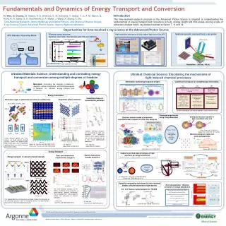
Explore the construction, working principles, and operating theories of single-phase induction motors. Learn about the double revolving field theory and how external torques initiate motor rotation without starting torque. Calculations and examples provide insights into performance.

E N D
EEE 360 Energy Conversion and Transport George G. Karady & Keith Holbert Chapter 7 Induction Motors 360 Chapter 7 Induction Motor
Lecture 22 360 Chapter 7 Induction Motor
Construction 360 Chapter 7 Induction Motor
7.6 Single Phase Induction Motor • The single-phase induction machine is the most frequently used motor for refrigerators, washing machines, clocks, drills, compressors, pumps, and so forth. • The single-phase motor stator has a laminated iron core with two windings arranged perpendicularly. • One is the main and • The other is the auxiliary winding or starting winding 360 Chapter 7 Induction Motor
7.6 Single Phase Induction Motor 360 Chapter 7 Induction Motor
7.6 Single Phase Induction Motor • This “single-phase” motors are truly two-phase machines. • The motor uses a squirrel cage rotor, which has a laminated iron core with slots. • Aluminum bars are molded on the slots and short-circuited at both ends with a ring. Figure 7.42 Single-phase induction motor. 360 Chapter 7 Induction Motor
7.6 Single Phase Induction Motor Figure 7.10 Squirrel cage rotor 360 Chapter 7 Induction Motor
7.6.1 Operating principle 360 Chapter 7 Induction Motor
7.6 Single Phase Induction Motor • The single-phase induction motor operation can be described by two methods: • Double revolving field theory; and • Cross-field theory. • Double revolving theory is perhaps the easier of the two explanations to understand • Learn the double revolving theory only 360 Chapter 7 Induction Motor
7.6 Single Phase Induction Motor 7.6.1 Double revolving field theory • A single-phase ac current supplies the main winding that produces a pulsating magnetic field. • Mathematically, the pulsating field could be divided into two fields, which are rotating in opposite directions. • The interaction between the fields and the current induced in the rotor bars generates opposing torque 360 Chapter 7 Induction Motor
7.6 Single Phase Induction Motor • The interaction between the fields and the current induced in the rotor bars generates opposing torque. • Under these conditions, with only the main field energized the motor will not start • However, if an external torque moves the motor in any direction, the motor will begin to rotate. Figure 7.43 Single-phase motor main winding generates two rotating fields, which oppose and counter-balance one another. 360 Chapter 7 Induction Motor
7.6 Single Phase Induction Motor 7.6.1 Double revolving field theory • The pulsating filed is divided a forward and reverse rotating field • Motor is started in the direction of forward rotating field this generates small (5%) positive slip • Reverse rotating field generates a larger (1.95%) negative slip 360 Chapter 7 Induction Motor
7.6 Single Phase Induction Motor 7.6.1 Double revolving field theory • The three-phase induction motor starting torque inversely depends on the slip • This implies that a small positive slip (0.01–0.03) generates larger torque than a larger negative slip (1.95–1.99) • This torque difference drives the motor continues to rotate in a forward direction without any external torque. 360 Chapter 7 Induction Motor
7.6 Single Phase Induction Motor 7.6.1 Double revolving field theory • Each of the rotating fields induces a voltage in the rotor, which drives current and produces torque. • An equivalent circuit, similar to the equivalent circuit of a three phase motor, can represent each field • The parameters of the two circuits are the same with the exception of the slip. 360 Chapter 7 Induction Motor
7.6 Single Phase Induction Motor 7.6.1 Double revolving field theory • The two equivalent circuits are connected in series. • Figure 7.44 shows the equivalent circuit of a single-phase motor in running condition. • The current, power and torque can be calculated from the combined equivalent circuit using the Ohm Law • The calculations are demonstrated on a numerical example 360 Chapter 7 Induction Motor
7.6 Single Phase Induction Motor Figure 7.44 Equivalent circuit of a single-phase motor in running condition. 360 Chapter 7 Induction Motor
7.6 Single Phase Induction Motor The results of the calculations are: • Input power: • Developed or output power: 360 Chapter 7 Induction Motor
7.6 Single Phase Induction Motor Figure 7.47 Single-phase motor mechanical output power and electrically developed power versus speed. 360 Chapter 7 Induction Motor
7.6.2.2 Starting torque 360 Chapter 7 Induction Motor
7.6 Single Phase Induction Motor • The single-phase motor starting torque is zero because of the pulsating single-phase magnetic flux. • The starting of the motor requires the generation of a rotating magnetic flux similar to the rotating flux in a three-phase motor. • Two perpendicular coils that have currents 90° out-of-phase can generate the necessary rotating magnetic fields which start the motor. • Therefore, single-phase motors are built with two perpendicular windings. 360 Chapter 7 Induction Motor
7.6 Single Phase Induction Motor • The phase shift is achieved by connecting • a resistance, • an inductance, or • a capacitance in series with the starting winding. • Most frequently used is a capacitor to generate the starting torque. 360 Chapter 7 Induction Motor
7.6 Single Phase Induction Motor • Figure 7.50 shows the connection diagram of a motor using a capacitor to generate the starting torque. • When the motor reaches the operating speed, a centrifugal switch turns off the starting winding. Figure 7.50 Single-phase motor connection. 360 Chapter 7 Induction Motor
7.6 Single Phase Induction Motor • The centrifugal switch is necessary because most motors use a cheap electrolytic capacitor that can only carry ac current for a short period. • A properly selected capacitor produces around 90° phase shift and large starting torque. Figure 7.50 Single-phase motor connection. 360 Chapter 7 Induction Motor
7.6 Single Phase Induction Motor Figure 7.51 Torque–speed characteristic of a small single-phase induction motor. 360 Chapter 7 Induction Motor
7.6 Single Phase Induction Motor • A less effective but more economical method using shaded pole motors • The motor has two salient poles excited by ac current. • Each pole includes a small portion that has a short-circuited winding. This part of the pole is called the shaded pole. • The main winding produces a pulsating flux that links with the squirrel cage rotor. • This flux induces a voltage in the shorted winding. 360 Chapter 7 Induction Motor
7.6 Single Phase Induction Motor • The induced voltage produces a current in the shorted winding. • This current generates a flux that opposes the main flux in the shaded pole (the part of the pole that carries the shorted winding). • The result is that the flux in the unshaded and shaded parts of the pole will be unequal. • Both the amplitude and the phase angle will be different. 360 Chapter 7 Induction Motor
7.6 Single Phase Induction Motor • These two fluxes generate an unbalanced rotating field. The field amplitude changes as it rotates. • Nevertheless this rotating field produces a torque, which starts the motor in the direction of the shaded pole. • The starting torque is small but sufficient for fans and other household equipment requiring small starting torque. • The motor efficiency is poor but it is cheap 360 Chapter 7 Induction Motor
7.6 Single Phase Induction Motor • The motor has two salient poles excited by ac current. • Each pole includes a small portion that has a short-circuited winding. • This part of the pole is called the shaded pole Figure 7.52 Concept of single-phase shaded pole motor. 360 Chapter 7 Induction Motor
7.6 Single Phase Induction Motor Figure 7.53 Shaded pole motor for household fan. 360 Chapter 7 Induction Motor