Download
1 / 30
300 likes | 330 Views
Explore the importance of mixing for different boiler types in radiant heating systems. Learn about various mixing options, valve types, and piping considerations. Understand system sizing, flow rates, head loss calculations, and resetting techniques for optimal efficiency. Discover the role of 3-way and 4-way valves, climate-based resets, and programming for improved performance. Wiring guidelines, circulator selection, and injection variations are also covered.

E N D
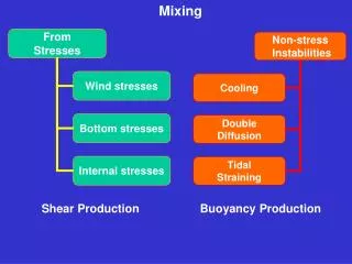
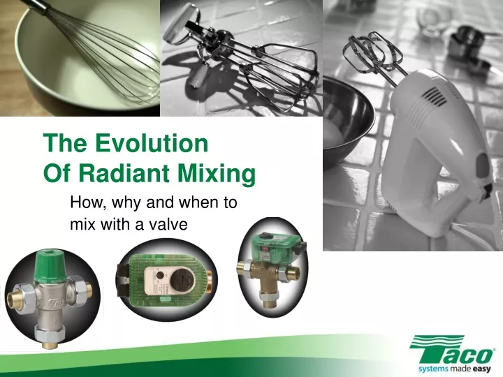
The Evolution Of Radiant Mixing How, why and when to mix with a valve
Why Mix? • CI boilers • Need lower temp for radiant • Multi-temp, multi-load • Zone by zone mixing • Mod/Con boilers • Boiler makes hi-temp • Need to mix for lower temp radiant • Zone by zone mixing
Mixing Options • 3-Way tempering valves • Motorized setpoint valves • Motorized reset valves
Mixing Options • 3-Way tempering valve • Fixed water temperature • Simple, thermostatic, non-electric • MUST ZONE radiant system properly/aggressively • Must pipe bypass to protect boiler
RadiantReturn 3-Way Tempering Valve Boiler Supply RadiantSupply Boiler Return
1800 Out Globe Valve Mix Point >1350 1150 Back Protecting The Boiler
BTUH 30,000 ΔT x 500 10 x 500 A System Sizing Problem • Find the flow rate • GPM = • GPM = • GPM = 6
1” pipe Sizing The Pipe • 2-4 GPM = ¾” • 4 - 8/9 GPM = 1” • 8-14 GPM = 1¼” • 14-22 GPM = 1½” • Based on maxvelocity of 4 feet per second forcopper 6 GPM = 1” pipe
Flow & Head Loss • Find radiant tube head loss • Measure total run • Multiply by 1.5 • Multiply by .04 • 4’ head/100‘ equiv. length • 60’ x 1.5 = 90 • 90’ x .04 =3.6 feet of head Radiant Tube Head Loss – 5’ 60 feet
What About The 3-Way Valve? • 5’ + 3.6’ = 8.6’ • 1” valve Cv = 3.8 • 3.8 GPM = 1psi • 1psi = 2.31’ head • (Flow 4 Cv)2x 2.31 = head loss • (643.8)2 = 2.5 psi • 2.5 X 2.31 = 5.8’ • 8.6 + 5.8 = 14.4’
iValve Reset • Outdoor reset – more effective, efficient system • Simple wiring – low voltage • Can reset individual zones • Provides boiler protection • Available in 2, 3 and 4-way models
Changing Conditions Fixed SWT Variable SWT • Heat loss change every day • Fixed water temp =variable run times = cycling in mild times • Variable water temp =fixed run times =less short cycling =greater efficiency
How Does It Know? • Four key numbers • Outdoor Design Temp • Mix Design • WWSD • Mix Start • Reset ratio = Mix Design Temp - 720 720 – Design Outdoor Temp
= 72 - 0 = 72 Let’s Do One… • Mix Design = 130, Outdoor Design = 0 • 130 – 72 • 58 0.8
What Does 0.8 Mean? • Radiant water temp increases 0.8 of a degree for every 1 degree drop in outdoor temperature • To program: • Move dial on iValve to correct ratio
Cast Iron Boilers • Reset the delivery • Boiler operates on high limit • Requires >1350 to prevent condensing • Boiler fires more effectively, efficiently • Take advantage of thermal mass • Can add boiler reset, as well
Mod/Con Boilers • Multiple water temperature system • Resetting off the reset • Lower return water temps • Greater efficiency
Wiring This Bad Boy… • 3 sensors • Boiler return, radiant supply,outdoor • Outdoor sensor on northside, out of sunlight, abovesnowline • 24v power in • Zoning/circulator controldone externally
4-Way Valve • One more hole… • Higher Cv • For higher flow rates • ¾” – 7 Cv • 1” – 9.3 Cv • Same wiring • MUST pipe primary-secondary!!!
Piping & Sizing 6 GPM, 5’ head radiant 1” pipe, 10’ total length = 0.6’ head ¾” valve = 1.7’ head Total head = 7.3’
Why No 1” Valve? • Could have, but… • 1” valve = 1’ head loss • Same circulator • Why not use less expensive valve? • Smaller valve – tighterwater temp control • Size valve to flow, notline size
2-Way iValve • Use for “injection” • Higher Cv than 3-way valves • ½” = 4.9 • ¾” = 10.3 • 1” = 8.9 • Can handle higher flowrate applications
Injection “Variation” • Injection without an injection circulator • Bypass, globe valve needed • Size to flow,not line size
30,00055 x 500 ½” 1” Pipe & Pump Sizing 30,000 BTUH1350 SWT 1250 RWT • 6 GPM, 5’ radiant head loss • Bypass, manifold supplypiping - 1” • Injection pipe sizing: • GPM = • GPM =1.09 • Valve/pipe = ½” • .11 feet of head through valve
Additional Features • Min/max system supply water temperature • Minimum boiler return temperature • Set with dipswitch – 120 or 135 • Disable by not installing boiler return sensor • WWSD -- 70 degrees or off