Download

1 / 80
820 likes | 1.02k Views
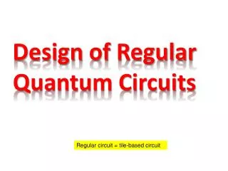
Design of Regular CLASSICAL AND Quantum Circuits. CLASSICAL LOGIC. Design of SRFPGA cell. General idea of SRFPGA architecture. SRFPGA layout With I/O pins. 1. Faults observed during column test C = 2. Test output. 0.

E N D
SRFPGA layout With I/O pins
1 Faults observed during column test C = 2. Test output 0 1 1 1 1 1 1 1 1 1 1 1 0 1 0 1 1 Var1 var2 var3 var4 var5 var6 var7 var8 var9 var10 var11 var12 var13 var14 var15 var16 I n p u t t e s t v e c t o r Faults observed during diagonal test D = 2 1 1 0 1 T e s t o u t p u t 1 1 1 1 1 1 1 1 1 Total number of Faults N = C * D = 2 * 2 = 4. 1 1 1 1 1 1 1 1 1 1 1 1 1 1 1 1 1 1 1 1 1 1 1 1 1 1 1 1 1 1 1 1 1 Input test vector
A logic gate is reversible if • Each input is mapped to a unique output • It permutes the set of input values • A combinational logic circuit is reversible if it satisfies the following: • Has only one Fanout, • Uses only reversible gates, • No feedback path, • has as many input wires as output wires, and permutes the input values. Reversible Permutative logic Gates and Circuits
Basic Reversible Gates NOT gate Controlled-NOT or Feynman gate a b a c 0 0 0 0 0 1 0 1 1 0 1 1 1 1 1 0
a b c a b f 0 0 0 0 0 0 0 0 1 0 0 1 0 1 0 0 1 0 0 1 1 0 1 1 1 0 0 1 0 0 1 0 1 1 0 1 1 1 0 1 1 1 1 1 1 1 1 0 Basic Reversible Gates Toffoli gate (Controlled-Controlled NOT gate)
Basic Reversible Gates Swap gate Implementation of Swap gate using controlled-NOT
Basic Reversible Gates Swap gate Implementation of Swap gate using controlled-NOT
a b c a f g 0 0 0 0 0 0 0 0 1 0 0 1 0 1 0 0 1 0 0 1 1 0 1 1 1 0 0 1 0 0 1 0 1 1 1 0 1 1 0 1 0 1 1 1 1 1 1 1 Basic Reversible Gates Fredkin gate (Controlled SWAP gate)
MMD: Transformation based • Gupta-Agrawal-Jha: PPRM based • Mishchenko-Perkowski: Reversible wave cascade • Kerntopf: Heuristics based • Wille: BDD based synthesis Popular Algorithms for Synthesis of Reversible Logic Circuits
Example of Agrawal-Jha Algorithm • PPRM form for each output in terms of • Input variables are given as follows and • node is created
Agrawal-Jha Algorithm (cont..) • Parent node is explored by examining each output variable in the PPRM expansion. • Factors are searched in the PPRM expansions that do not contain the same input variable. • For example in the expansion below appropriate terms are “c” and “ac” • The substitution is performed as • In this example OR
Agrawal-Jha Algorithm (cont..) New nodes are created based on substitution
Common problem with current approaches: they invariably use nxnToffoli gates, that might imposes technological limitations. • High Quantum cost of Toffoli gates with many inputs. • Synthesize only reversible functions, not Boolean functions that is not reversible. Problem with Current Synthesis Approaches
Quantum Cost of 4x4 Toffoli Gate • Implementation of 4x4 Toffoli gate with Quantum realizable 2x2 primitives such as controlled-V, controlled-NOT, controlled-V+.
Expansions Rules for Lattice DIAGRAAMS • Positive Davio Tree can be created by expanding PPRM function using positive Davio expansion. • Positive Davio Lattice is created by performing joining operation for neighboring cells at every level. • Other Lattices can be created using similar method but using expansions such as Shannon or Negative Davio expansions or combination of them.
On the previous foils I showed representation of the Davio and Shannon cells as cascade of reversible gates. • Next I present unique method to create Quantum Array from Positive Davio Lattice. • The same approach can be used for other Lattices. Creating Quantum Array from Lattices
Creating Positive Davio Lattice • Each node represents pDv cell.
Creating Quantum Array from Positive Davio Lattice + c 1 + + 1 d d 1 + + 1 1 b b + + + 1 a 1 1 a 1 1 a 1 + 1 1 d 1 0 1
Å 1 a Å 1 ad Å Å 1 ab b Å Å Å Å Å b a d bd b abd a Å Å Å Å Å Å Å 1 db ad abd bc ac cd bcd Å Å Å 1 db abd ad Quantum Array Representation a b c d garbage d 0 garbage 1 garbage 1 garbage 1 garbage a 0 1 function
Å 1 a Å 1 ad Å Å 1 ab b Å Å Å Å Å b a d bd b abd a Å Å Å Å Å Å Å 1 db ad abd bc ac cd bcd Å Å Å 1 db abd ad Quantum Array Representation a b c d garbage d 0 garbage 1 garbage 1 garbage 1 garbage a 0 1 function
Creating Positive Davio Lattice • Each node represents pDv cell.
Reversible circuit synthesized with only 3x3 Toffoli gates. • Generates reversible circuit for any ESOP. • Adds ancilla bits but overall cost of the circuit will be lower due to use of low cost 3x3 Toffoli gates. Advantages of Lattice to QA
Dipal cell representation with Shannon cell reversible gates a a a = Å f a b a c b = Å f a b a c b c Å c b c Development ofDipal gate • Dipal gate is a reversible • equivalent of Shannon cell • There are 23! = 8! = 40320 3x3 Reversible logic functions, however only handful of them shown earlier are useful for synthesis purpose.
Dipal cell with negative variable represented with Shannon cell with negative reversible gates variable a a a = Å b f a c a b Å b c b c = Å c f a c a b Development of Dipal gate (cont..)
Dipal cell representation with Shannon cell reversible gates a a a = Å f a b a c b = Å f a b a c b c Å c b c Development ofDipal gate • Dipal gate is a reversible • equivalent of Shannon cell • There are 23! = 8! = 40320 3x3 Reversible logic functions, however only handful of them shown earlier are useful for synthesis purpose.
Dipal gate unitary matrix 000 001 010 011 100 101 110 111 000 001 010 011 100 101 110 111
Results with Pdv Lattice and comparison with MMD and AJ results
Results with Pdv Lattice and comparison with MMD and AJ results (cont..)