Download
1 / 22
230 likes | 396 Views
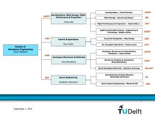
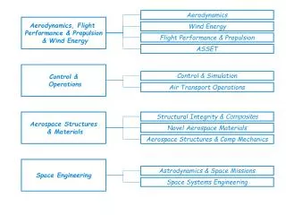
Aerodynamics and Aeroelastics, WP 2 Flemming Rasmussen Aeroelastic Design Wind Energy Department Risø DTU. WP2 Aero-dynamics and Aero-elastics OBJECTIVES. Overall: To develop an aeroelastic design basis for large multi MW turbines. Specific:.

E N D
Aerodynamics and Aeroelastics, WP 2 Flemming Rasmussen Aeroelastic Design Wind Energy Department Risø DTU
WP2 Aero-dynamics and Aero-elastics OBJECTIVES Overall: To develop an aeroelastic design basis for large multi MW turbines. Specific: • Development of nonlinear structural dynamic models (modeling on the micromechanical scale is input from WP3). • Advanced aerodynamic models covering full 3D CFD rotor models, free wake models and improved BEM type models. (The wake description is a prerequisite for the wake modeling in WP8). • Models for aerodynamic control features and devices. (This represents the theoretical background for the smart rotor blades development in WP 1.B.3) • Models for analysis of aeroelastic stability and total damping including hydroelastic interaction • Development of models for computation of aerodynamic noise.
WP 2.1 Structural dynamics, large deflections & non-linear effects • Approach • Identification of important non-linearities in large wind turbines • Challenge: predict blade torsional deformation in loaded case • Bending-Torsion coupling When blade flap curvature w’’ becomes large, bending moment Mζ contributes significantly to blade torsion moment My.
WP 2.1 Non-linear effects (analytical study) • Additions to the baseline, 1st-order, model • Formulation of dynamic equations in the deformed state (same structural couplings as in baseline but 2nd-order kinematics and dynamics) (2nd order beam-0) • Tension – torsion coupling terms (2nd order beam-1) • Bending – torsion coupling terms (2nd order beam-2) • Pre-twist – torsion coupling term (2nd order beam-3) Wind speed: 11m/s
WP 2.1 Non-linear effects Linear vs. non linear beam model analysis, NTM at 11.4 m/s
WP2.2 Advanced aerodynamic models • Objectives • to identify the limitations in the engineering aerodynamic modeling in BEM type codes • Approach • inter comparison of results of models of different complexity applied on MW rotors, RWT- 5MW • Simulation cases • uniform inflow on RWT turbine (stiff model) • strong wind shear in inflow • unsteady inflow (turbulent)- not yet performed
Blade normal force distribution Simulations with various codes at 8 m/s uniform inflow
Wind speed with height, night- day, Høvsøre from http://veaonline.risoe.dk
Measured inflow angle on the NM80 at Tjæreborg during a period with strong shear and low turbulence Inflow angle
WP2.2 Blade normal force 8 m/s - strong inflow shear - exponent 0.55, blade up blade down
WP2.2 Blade normal force 8 m/s -- strong inflow shear - exponent 0.55 blade 90 deg. blade 270 deg.
WP 2.3 Advanced control features and aerodynamic devices Approach: • Develope detailed models for analysis of a few promising flow control concepts (in close corporation with WP 1A5). • Deformable camberline.
Dynamic Stall: Harmonic Alpha and Beta • Blue: Alpha and Beta in phase • Black: No Beta • Red: In counter-phase (180 shift)
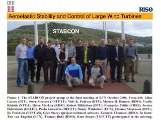
WP 2.4: Aeroelastic stability and total damping including hydrodynamics • Approach: • Aerodynamic damping and aeroelastic stability of the RWT 5 MW turbine • Blade structural damping model • CFD-structure coupling
WP 2.4: Aerodynamic damping of blade modes for RWT 5 MW First flapwise mode First edgewise mode
WP 2.5 Computation of aerodynamic noise– coupled CFD-CAA models Approach: Improve computation of aerodynamic trailing edge noise. Input from CFD simulations of boundary layer parameters at trailing edge. Validation: Eksperimental data on both aerodynamics and aeroacustics
Test Cases : VTE Model Developed at LWT (SIROCCO Project) • goal: variation of boundary-layer parameters at trailing-edge • requires strong contour change over major part of chord length • three variations: VTE_lin, VTE_kav (and VTE_vex) Wind tunnel model with adjustable shape
WP2 Aerodynamics and Aeroelastics • Summary • Bending-torsion coupling is important • Inflow shear is non-trivial • Dynamic stall model for variable trailing edge • Stability analysis including non-linear effects (and structural modal damping prediction) • Noise prediction: Boundary layer predictions and measurements