Download
1 / 45
660 likes | 1.46k Views
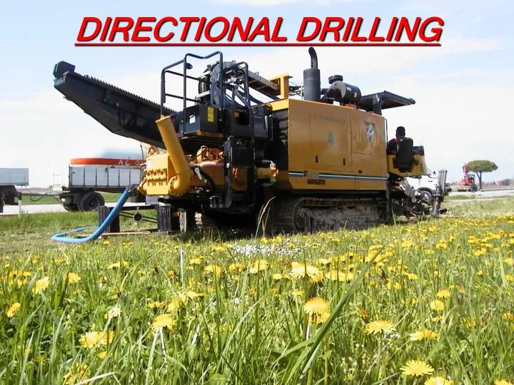
DIRECTIONAL DRILLING. I TALIAN A SSOCIATION FOR T RENCHLESS T ECHNOLOGY. SEMINAR ON NON INVASIVE TECHNOLOGIES NO-DIG (Trenchless) TECHNOLOGIES HORIZONTAL GUIDED DRILLING AMMAN 21st-23rd march 2009 Dr. Esposto Feliciano (Resp.le Pianific. e MKT Soc. Anese S.r.l. (Segr. Gen. IATT).

E N D
ITALIAN ASSOCIATION FORTRENCHLESS TECHNOLOGY SEMINAR ON NON INVASIVE TECHNOLOGIES NO-DIG (Trenchless) TECHNOLOGIES HORIZONTAL GUIDED DRILLING AMMAN 21st-23rd march 2009 Dr. Esposto Feliciano (Resp.le Pianific. e MKT Soc. Anese S.r.l. (Segr. Gen. IATT)
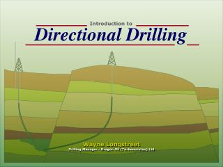
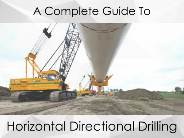
WHAT ARE WE TALKING ABOUT: HORIZ.DIRECTIONAL DRILLING (1) • This method is worldwide called HDD ( Horizontal Directional Drilling): • Guided Drilling • Horizontal Directional Drilling • In Italy it is commonly called : Trivellazione Orizzontale Teleguidata (T.O.T.) Trivellazione Orizzontale Controllata (T.O.C.)
HDD Main Characteristics (3) The HDD Technique enables : • to control the drilling head • to monitor continuously the drilling head position. • The Process is carried out in three phases: 1. Realization of the pilot drilling hole 2. Reaming phase/phases 3. Pipe Laying
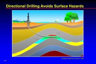
1 ExitPit HolePath Drilling Head Directional Drilling
2 Coil Reaming Head HDPE Pipe Directional Drilling
Topography MainSpecifications Necessary requirements to carry out an HDD Project Necessary documentation for the surface evaluation : • Map of the work site area • Overmap of the whole path • Longitudinal profile • Localization of water steams • Work area design • length, distance from civil and residential infrastructures, • Stratigraphy and localization and dimension of possible obstacles • Seabed morphology – Safety distance
Geology • Evaluation of existing documents • Case “history” • Soundings • Penotrometer Testing • Geophysical Investigation • Laboratory Test • Geotechnical Report • Related to nearby pre-existing constructios (geological maps) • Existing installations, abbandoned constructions … • Magnetostraigraphy and ground peculiarities • Cone Penetration Test (CPT) • Standard Penetration Test (SPT) • Electro Magnetic Reflection (EMR or “georadar”), Geoelettrical Measurement, Earthquake evaluation • On non -cohesive and non -solid material, on cohesive material, on rocks • Helps to determine the most appropriate operational methods
Additional information Various information • Necessary assessment of hydrographic pressure • Position, depth and cable typology, pipes,conducts located nearby or across the drilling path • Dimensions and localization of pre-existing sub-soil utilities • Weather and sea forecast , macro-water streams, water specifications (pH, Salinity) • Basal Groundwater Level • Existing Sub-soil utilities • Basement and Civil Work • Information on Climate and Hydrographic Datas
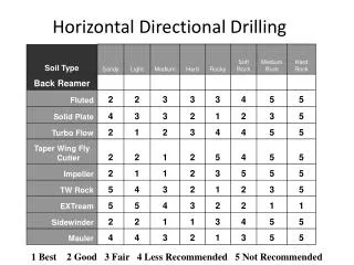
Soil Compounds Peculiarities Geology • Jetting, cutting, reaming • Hole stability, Resistence to mudslides and leakages • Transportation ,cuttings • Pulling Force Ground Typology • Cohesive: - clay, peats, slimes • Non cohesive - gravel, sand, slimes, • Rocks
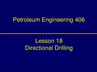
DIRECTIONAL DRILLING • Derived application from thepetrol field(first steps in the 30’s – USA) • In the 60’s first non guide drilling experiments (USA) • In Europe from the 80’s onward • In Italy first relevant experiments with Snam in the 80’s • Significant Development in Italy: in the 90’s (telecommunications) N.b.: inl 2000 – Used drilling machines : USA 8000, Germany 400, Italy 60. In 2008.............3-5 volte?????????? Applications • Telecommunication ducts • Pipelines for water transportation and distribution • Sewage pipes • Gaz and fuel transportation and distribution • Electrical conducts and cables • Tele-heating pipes • Draining and evacuation Tubes
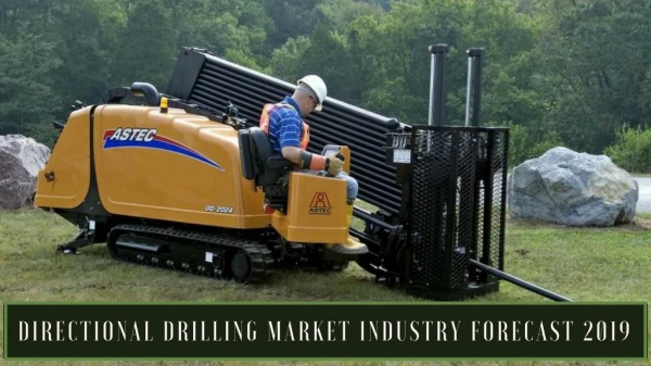
DRILLING PROCESS Classification DIRECTIONAL DRILLING • Basic Compounds : • Drilling Units • Guidance System • Drilling Muds • Drill string including drilling rods, tricones , reamers and pulling elements • Mixing units, pumping , filtration and mud recycling • MICRO (Pulling force max 6t) • MINI (Pulling force from 6 to 20 t) • MIDI (Pulling force from 20 to 50 t) • MAXI (Pulling force from 50 to 250 t) • MEGA (Pulling force superior to 250 t)
DRILLING PHASES Initial Phase : Pilot Hole Drilling • Initial small sized pilot hole from pit entry to pit exit following a previously defined profile. • Drilling Control through a “drilling head” + magnetic detector • Drilling through pushing and rotation • Cutting carried out on the ground through : • a) mechanical action through tricone and mud pulling motor • b) hydrodynamic cutting through drilling head • Drilling Control by means of guidance system
Second phase: Reaming DRILLING PHASE • Pilot hole widening through adequate machine tools • The reamer is used as substitute for the drilling head • Drilling through rotation and pulling towards the rig • Logistic coupling of new rods • Possibility / necessity of extra-reaming in case of increased diametres • Friction reduction • Fluid recycling • Lubrificating liquids/materials
Third phase: Pipeline pulling and laying DRILLING PHASES Pipeline Pulling from the exit pit to the rig • Interposition of reaming rods and pipes • Use of a swivel joint • Coupling to the pulling head • N.b.: Pipes pulling system (catenary)
Drilling Tools DRILLING PHASES Axial Assimetry • Deviation = stop to rotation and pushing • Linear Trajectory stability = rotation
Drilling Fluids DRILLING PHASES • Density 1,02-1,06 g/cm3 • Viscosity related to ground typology (40-60 sec) • pH – ione calcium >8 • Sand contents 2% • Gel strength, Yield point, • Filtered material control Proprieties Control • Water, bentonite, polymers mixing
Guidance System DRILLING PHASES WALK-OVER • Radio transmitter • Surface detector • Depth, inclination, orientation, direction, temperature, ... • Max Depth 10m • No azimuthal angle measure • Pitch Resolution 0,1% • Depth Precision ± 5% • Sensitivity to electromagnetical interferences (active/passive) • Necessity di access vertically to the bore (remote control)
Guidance System DRILLING PHASES WIRE-LINE • Radio translmitter + wire-line • Detector on surface • Depth, inclination, orientation, direction, temperature, ... • Max Depth 20m • No measure of the azimuthal angle • Pitch Resolution 0,1% • Depth Precision ± 5% • Sensitivity to electromagnetical interferences(active / passive) • Necessity to access vertically to the bore (remote control) • Constant awareness of inclination and orientation
Guidance System DRILLING PHASES MAGNECTIC SYSTEMS • System provided with magnetometres e inclinometres. • Cable Line • Localization of the azimuthal angle • Data elaboration through specific software • No Depth limit • Pitch resolution 0,2% • Depth Precision ± • Limited sensitivity to electromagnetical interferences (active / passive) • Remote control Coordinates x,y,z Possibility of interference contrast system Tru-track, Para-Track, Beacon
HORIZONTAL GUIDED DRILLING The Project The channel mouth crossing is characterized by two parallel ducts which exiting from the ground in proximity of the channel banks, penetrate underneath the channel and the planned works. Ducts “A” Typology: 9 Polyethylene ducts Ø 140mm Drilling Length : ~ 950m Max Depth: - 43,50m s.l.m.m. Exit bore Diametre: 900 mm Ducts “B” Typology: 6 Polyethylene ducts Ø 140mm Drilling length: ~950m Max Depth: - 44,50m s.l.m.m. Exit bore Diametre: 760 mm
Bocca di Chioggia Panorama CASE HISTORY
Bocca di Chioggia The Rig CASE HISTORY
Bocca di Chioggia Work site Area CASE HISTORY
HORIZONTAL GUIDED DRILLING Sistema di guida
HORIZONTAL GUIDED DRILLING Operational Phases Pilot Bore: command cabin Tube preparation Initial Pulling Pulling: tools and tubes entry
Cavarzere VENETO ACQUE S.p.A. The Project Adige river and Gorzone Channel Crossing • Length: 600,00m • Depth from p.c.: 35,00m • Pilot bore: diam. 254mm • Final reaming: diam. 1354mm • Infrastructure: DN 1000 Steel Penstock Thickness14,2mm +PEAD • Tube total weight : 213 t
HDD Riva del Garda Comune di Riva del Garda Boosting of the municipal water pipeline The project New pipeline from source • Length: 275,00m • Depth da p.c.: max 100,00m coverage • Level gap: > 170,00m • Ground: Calcium rock (Resistence Compr. 800-1000 kg/cm2 • Pilot bore: diam. 254mm • Reaming: 12”1/4 – 17”1/2 • Infrastructure: Pead tubes DN 280mm
San Giobbe - Venezia Laying of optical fibre cables Length: 230,00m Depth: -24,00 m s.l.m.m. Planimetrical deviation: ~ 80°
San Polo - Venezia Laying of anti-fire network – Vesta S.p.A. Diametre: DN 125, DN 225 Pead Length: L max= 90m Totale = 1740,00m+440,00m (Ø225mm) L max= 90m Totale = 1100,00m (Ø125mm) 60 site works (10 channel crossings) Depth: variabie (max -7,00 s.l.m.m.; medio -2,00 da p.c.) Objective: maximum reduction of surface deterioration reduced interference with existing networks
Venezia Laying of anti-fire network– Vesta S.p.A. Ingresso Uscita S. Giacomo Dell’Orio …ore 12:30
Venezia Laying of anti-fire network – Vesta S.p.A. Canareggio - Calle del Forno
Venezia Laying anti-fire network – Vesta S.p.A. Campo S. Maria Formosa Ø225mm L=50,00m
Venezia Laying of anti-fire network – Vesta S.p.A. Campo de la guera Calle de le bande
San Pietro in Volta - Pellestrina Sewer – Construction of main collector Strada della Laguna Length: total >2300,00m (distances up to 240,00m) Depth: variable fino a -4,50 m da p.c. Sloping : 0,3% ( gravity sewer) Infrastructure: Pead DN315, DN 250, DN110 (pressure)
Bocca di Malamocco The project CASE HISTORY
Bocca di Malamocco The Project CASE HISTORY
Bocca di Malamocco Pilot boring phase CASE HISTORY
GRAZIE PER L’ATTENZIONE esposto.feliciano@virgilio.it Tel.: +39-3937800003