Download
1 / 22
220 likes | 396 Views
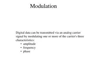
Modulation. Kevin Bolding Electrical Engineering Seattle Pacific University. Digital Transmission of Analog Data. Analog signal. Sampling. Convert to discrete samples (time domain). Quantizing. Convert to discrete levels (amplitude). Digital data.

E N D
Modulation Kevin BoldingElectrical EngineeringSeattle Pacific University
Digital Transmission of Analog Data Analog signal Sampling Convert to discrete samples (time domain) Quantizing Convert to discrete levels (amplitude) Digitaldata Optionally re-map to a different logical code (may expand) Coding Modulation Map to a physical code at desired frequency band Transmission Amplify and transmit
Sampling theorem: If sample rate >= 2x max frequency (f) And samples have infinite precision (analog) Can reproduce signal exactly after filtering out frequencies >f Sampling Quantizing Coding Modulation Transmission Sampling 15 14 13 12 11 10 9 8 7 6 5 4 3 2 1 0 • Undersampling • If sample rate is < 2f then it is possible to map multiple waveforms to the data (aliasing) Pulse-Amplitude Modulation – PAM Samples have analog (infinite precision) values
PCM: Approximate analog samples with a discrete sample n bit sample 2n levels Sampling Quantizing Coding 7 8 10 13 13 12 10 7 2 1 1 1 2 5 7 8 Modulation Transmission 15 14 Pulse Code Modulation 13 12 11 10 9 8 7 6 5 4 3 2 1 0 • Errors • Not analog, so quantizing error is present • Each additional bit halves the quantizing error (in volts) • SNR is Power ratio (proportional to V2) • Each extra bit used increases SNR by factor of 4 (6 dB) • N bits Signal/quantization error = 4n or 6n dB For n-bit quantization, the SNR =6.02(n) + 1.76 dB
Sampling Quantizing Coding Modulation Transmission Coding • Coding is the substitution of one digital code for another digital code • Incoming bit stream is assumed to be unencoded – raw bits (‘0’ means ‘0’ and ‘1’ means ‘1’) • Substitute code may alter or add to the bit stream in a way that can be inverted • Purposes of coding • Encryption • Redundancy to help with error detection and correction • Coding is addressed separately (later)
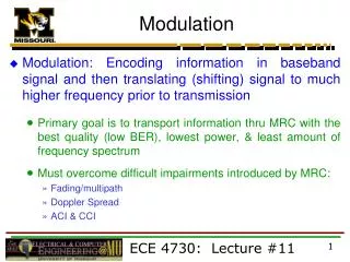
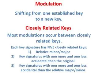
Sampling Quantizing Coding Modulation Transmission Modulation • Modulation: Alteration of one wave (carrier) to carry information provided by another (signal) • Amplitude Modulation • Frequency Modulation • Phase Modulation • If the Modulating signal is a digital signal, we have a wider variety of choices • Vary amplitude, phase, or frequency • ASK, PSK, FSK • Send more than one bit per symbol • Vary more than one aspect at the same time • QAM – varies both amplitude and phase • For digital data transmission, the Bit Error Rate is the measure of performance
Sampling Quantizing Coding Modulation Transmission Bit Error Rate • Digital signal quality is measured by the Bit Error Rate • Number of errors per bit transmitted, usually assuming uniform, non-correlated noise • For example, BER of 10-6 means an average of one error per million data bits transmitted
Sampling Quantizing Coding Modulation Transmission Bit Errors From Noise • If the SNR is too low, errors occur • If the noise causes the signal to cross the threshold, the bit will be read in error Errors from noise Threshold
Sampling Quantizing Coding Modulation Transmission Bit Errors from Bandwidth Limited ISI • If the bandwidth is too low so pulses spread out • Sequential pulses start to overlap and interfere with each other • Inter-symbol Interference (ISI) Pulse-spreading Threshold
Bit Errors from Delay ISI • Multiple paths (due to reflections) have different lengths • Each path has a different delay • Reflections overlap and spread out • Inter-symbol Interference (ISI) Image source: http://www.complextoreal.com/chapters/isi.pdf
Sampling Quantizing Coding Modulation Transmission Energy ratio E/N0 as a Measure of Quality of Signal • The “quality” of a modulated signal increases with: • Increased Signal-to-Noise ratio (S/N) • Increased bitRate-to-Bandwidth ratio (B/R) • A combined metric can be formed by multiplying these • E/N0 : Energy per bit / Noise power density • Similar to SNR, but also accounts for the bandwidth used • Normally expressed in dB • Equal to SNR if transmitting 1bit/Hz • S/N * B/R = SB/NR = (S/R) / (N/B)S/R = signal power / bits / time = (signal power)(time)/bits = Energy per bit = E or EbN/B = Noise power / Bandwidth = Noise power density = N0
Sampling Quantizing Coding Modulation Transmission Energy ratio and BER • Higher E/N0 means more “resources” available to a signal • Resources = SNR and bandwidth • Real measure of quality is the BER • For a given modulation scheme, we can plot the BER vs. E/N0 • We want BER to be low • We expect BER to go down with increased E/N0 Worse Better
0 1 0 1 1 1 0 1 0 0 0 1 0 1 p, if s(t) = 1 F(t)= 0, if s(t) = 0 Sampling BPSK Recovery (Coherent) Quantizing X BPSK Data out LPF Coding Modulation Recovered Carrier Transmission Binary Phase Shift Keying • Use PM techniques • Use phase angles (usually 0 and p) • Coherent Recovery (BPSK):In-phase carrier availableat receiver. • Incoherent Recovery (DPSK):Differential encoding allowsrecovery without carrier
BPSK uses two phase angles, 0 and p Two possibilities for symbol One bit per symbol p 0 0,-1 0,1 BPSK 3p/4 p/4 1,1 1,-1 Sampling -1,-1 Quantizing -1,1 7p/4 5p/4 Coding QPSK Modulation Transmission QPSK • Noise causing phase change within +/- p/2 will not cause error • If we use more phase angles, we can send more data per symbol • Quadrature (or Quaternary) PSK • QPSK uses angles p/4, 3p/4, 5p/4, 7p/4 • Four possibilities for symbol Two bits per symbol • Noise causing phase change within +/- p/4 will not cause error • Symbol error rate twice as high as BPSK, but sends twice as many bits/second Efficiency tie?
Sampling QPSK Generation Q = Quadrature Phase Carrier (sine) X 3p/4 p/4 Quantizing I=1,Q=1 I=-1,Q=1 + Data QPSK Splitter p/2 Coding I = In Phase Carrier (cosine) X I=-1,Q=-1 I=-1,Q=1 Modulation 7p/4 5p/4 Transmission Generating QPSK • Generate two signals in quadrature to each other (p out of phase) • Cosine and Sine work well • Horizontal axis is the I-axis, Vertical is the Q-axis • Represent bits: 0 -1, 1 +1 • Group consecutive bits together in pairs; first bit is value is I, second is Q • Multiply coordinates by the I and Q carriers and add
Sampling Quantizing Coding Modulation Transmission QPSK Waveform I=1,Q=1 I=-1,Q=1 I=-1,Q=-1 I=1,Q=1 I=1,Q=-1
Sampling Quantizing Coding Modulation Transmission Constant Envelope Modulation • Signal is sent by modulating the phase or frequency of carrier • BPSK, QPSK are the most common • No signal is modulated on the amplitude • Distortion of carrier amplitude does not affect the signal • Can be linear or nonlinear in digital mobile systems
Sampling Quantizing Coding Modulation Transmission QPSK Signal Transition Diagram • Shows transitions possible from one state to the next • In QPSK, all transitions are possible • The diagonal transitions create a particularly abrupt change in phase • Create large sidelobes outside of the primary band
Sampling Quantizing Coding Modulation Transmission Offset QPSK Modular Circuit
Sampling Quantizing Coding Modulation Transmission OQPSK Signal Space
Sampling Quantizing Coding Modulation Transmission p/4 QPSK ODD X ~ p + /4 p /2 X EVEN Every othersymbol
Sampling Quantizing Coding Modulation Transmission p/4-QPSK Signal Space Diagram (0, 0)B (0, 1)A (0, 0)A (0, 1)B (1, 0)B (1, 1)A (1, 0)A (1, 1)B