Download
1 / 31
320 likes | 507 Views
Graphics II 91.547 Shadow Maps Reflections. Session 5. Shadow Maps. Light Source. Objects. Eye Point. Shadow Maps: The algorithm. 1. Transform the scene objects to the light source coordinates (x’,y’,z’). 2. Disable color buffer writing and render the scene

E N D
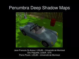
Graphics II 91.547Shadow MapsReflections Session 5
Shadow Maps Light Source Objects Eye Point
Shadow Maps:The algorithm 1. Transform the scene objects to the light source coordinates (x’,y’,z’). 2. Disable color buffer writing and render the scene objects into the z - buffer 3. Copy this buffer into a “shadow z - buffer” 4. Transform the scene back to the eye coordinates (x,y,z). 5. Render the scene. At each pixel, if a point on a surface is deemed to be visible, it is transformed into light source coordinates: (x,y,z) -> (x’,y’,z’). The x’ and y’ coordinates are used to index into the shadow z-buffer and z’ is compared with the z value in the buffer. If z’ is greater than this value, the point is in shadow and it is rendered as if the light is turned off. 6. Repeat for other light sources, and accumulate color
Shadow MapsTradeoffs • Excellent for situations when shadowing and shadowed objects are both complex • Some graphics systems do not provide necessary primitives or buffers • Aliasing is a problem • Possible solutions • Use high - resolution shadow z buffer • Jitter shadow texture to smooth out edges • Difficult to find appropriate projection when light source is in the middle of scene objects
Finite light sources produce“soft shadows” Finite size light source Shadowing object
Simulating finite size light source byMultiple point sources: “dithering” Light source moves in grid Shadowing Object (polygon) Plane of projection Shadows are “accumulated”
The Accumulation Buffer Color Planes Color data Accumulation Buffer
Accumulation buffer use: void glAccum(glenum op,glFloat value); op: GL_ACCUM reads each pixel from buffer currently selected for reading and multiplies RGBA values by value and adds the result to accumulation buffer. GL_LOAD reads each pixel from the buffer currently selected for reading, multiplies RGBA values by value and replaces values in accumulation buffer. GL_RETURN takes values from the accumulation buffer, mutiplies them by value, and places them in the color buffer. GL_ADD, GL_MULT adds or multiplies the value of each pixel in the accumulation buffer by value and returns it to the accumulation buffer.
Accumulation Bufferop = GL_ACCUM Value Color Planes Accumulation Buffer S X
Accumulation Bufferop = GL_LOAD Value Color Planes Accumulation Buffer X
Accumulation Bufferop = GL_RETURN Value Color Planes Accumulation Buffer X
Accumulation Bufferop = GL_MULT Value Accumulation Buffer X
Projection ShadowsCode example. 120 goto 240
Reflections Direct ray Eye point Reflected ray Plane of Reflection
Reflection Transformations:across major planes of symmetry Y- Z Plane X - Z Plane X - Y Plane
Reflection transformations:the general case Arbitrary plane X - Z plane
Reflection Transformations:the general case - constructing the transformation Inverse transformation Reflection across X - Z Plane Transformation to move reflecting plane to X - Z plane
Reflections:Visibility Issues Real Cone Real Ball Eyepoint Finite Size Reflecting Object Reflected Ball Not Visible Reflected Cone
Reflections:Visibility Issues “Reflected Cone” Should not be visible Eyepoint Finite Size Reflecting Object Real Cone Should be obstructed by reflecting object
Solution to visibility issues:use stencil and z buffer The algorithm: 1. Disable the depth test 2. Set stencil operation to replace with 1 3. Draw the reflecting polygon 4. Set the stencil operation to only draw where stencil=1 5. Multiply reflecting transformation onto modelview matrix 6. Enable depth test, render objects. Clip objects that are on opposite side of the reflecting plane from eyepoint. 7. Disable stencil test 8. Remove reflection transformation from modelview 9. Disable writing to color buffer 10. Draw the reflecting polygon 11. Enable writing to color buffer 12. Render the scene (unreflected)
Projection ShadowsCode example. 120 goto 240
Arbitrarily shaped reflective object. Eye point
Calculation of Texture Coordinates For each vertex, the reflected vector direction is given by: Let m be defined as: The texture coordinates are given by:
Sphere Mapping:The OpenGL Algorithm 1. Bind the texture containing the sphere map. 2. Set sphere mapping texture coordinate generation: glTexGen(GL_S, GL_TEXTURE_GEN_MODE, GL_SPHERE_MAP); glTexGen(GL_T, GL_TEXTURE_GEN_MODE, GL_SPHERE_MAP); 3. Enable texture coordinate generation: glEnable(TEXTURE_GEN_S) glEnable(TEXTURE_GEN_S) 4. Draw the object, providing correct normals on a per- face or per-vertex basis.
Obtaining the Sphere Map Manually Reflective Sphere at object location Camera