Download

1 / 30
300 likes | 456 Views
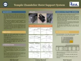
Temple chandelier Hoist Support System. BYU Capstone Nick Barnwell, Andrew Marshall, Matt Steward April 15, 2014. Components. Hoist. Safety Strap. Electrical Reel. Pulleys. configurations. Structural support. One way. Two way. Three way. Spatial and design Requirements.

E N D
Temple chandelier Hoist Support System BYU Capstone Nick Barnwell, Andrew Marshall, Matt Steward April 15, 2014
Depending on how far the chandelier needs to drop will determine the required minimum distance between the hoist and the first pulley. As a rule of thumb, if the distance is greater than or equal to 10feet the distance requirement will always be met. If a shorter distance is desired calculations* will need to be done to find the minimum distance allowable. Hoist-pulley distance requirements *Example calculations in the appendix of the hand out
Dynamic Load Factor *Dynamic Load Factor calculations in the appendix of the hand out
The mounting plate was designed for worst case scenarios and against all expected failure modes. • A minimum required thickness was determined from these calculations* and rounded up to 0.5”. • The plate width and length may be adjusted according to which system components will be attached to it. • The chandelier hoist, electrical reel, and safety strap will all fit on a 3’ x 3’ plate. Plate Design *Plate design calculations in the appendix of the hand out
Beam Design *Beam design calculations in the appendix of the hand out