Download
1 / 29
310 likes | 466 Views
Radiation Directivity of Human and Artificial Speech. Teemu Halkosaari 1 & Markus Vaalgamaa 2 1 Helsinki University of Technology, Laboratory of Acoustics and Audio Signal Processing 2 Nokia Technology, Audio Quality e-mail: markus.vaalgamaa@nokia.com

E N D
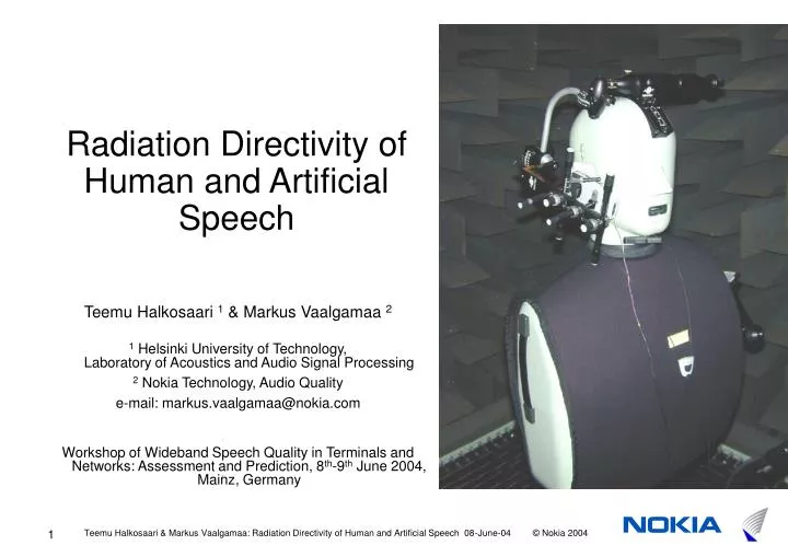
Radiation Directivity of Human and Artificial Speech Teemu Halkosaari 1 & Markus Vaalgamaa 2 1 Helsinki University of Technology, Laboratory of Acoustics and Audio Signal Processing 2 Nokia Technology, Audio Quality e-mail: markus.vaalgamaa@nokia.com Workshop of Wideband Speech Quality in Terminals and Networks: Assessment and Prediction, 8th-9th June 2004, Mainz, Germany
Agenda • Motivation and Background • Goal • Measurements • Analyzes • Modelling • Results • Improvements to telephonometry • Conclusions Part I: WHY? Part II: The STUDY Part III: The OUTCOME
Part IWHY? • Motivation and Background • Goal
Part I: WHY? 1. Motivation and Background • Artificial mouths and HATS were originally designed for narrowband speech measurements with big landline handsets. • In past years, the size of phone has become smaller and use of headsets is becoming common. • In future, wideband phones are coming… • It seems that HATS and artificial mouths will be used in future, although • we do not know exactly the directivities of artificial mouths or • human mouth especially on near field locations • Additional interesting topic is that how does the speech content affect to the directivity? • Extensive literature on the subject is not available • Standardization is inadequate • ITU-T P.58 Head and torso simulator for telephonometry • ITU-T P.51 Arficial mouth • narrow band: 300-3400Hz, wide band: 150-7000Hz
Part I: WHY? 2. Goal • Measure frequency responses for artificial mouths to positions where microphones of handsets and headsets are situated. • Repeat the same measurements for a group of test subjects • Most important part of the study is to analyze the difference between artificial mouths and an average person. • In practice a set of transfer functions is acquired.
Part IIThe STUDY • Measurements • Analyzes • Modelling • Results
Part II: The STUDY 3. Measurements: Arrangements • Two separate systems • Test subjects were measured in Helsinki University of Technology, anechoic chamber, 8 channel parallel recording system. • Artificial mouths were measured in Nokia facilities in Salo, Finland, anechoic chamber, Audio Precision APwin measurement system, 2 channel parallel MLS measurement. • Probes • B&K 1/8 and ¼ inch measurement microphones • 8 Sennheiser KE-4-211-2 electret microphones • In addition, some phones: large and small handset, and accessories: boom headset, mono and stereo headsets, were measured
Part II: The STUDY 3. Measurements: Positions • Referred to • lip plane and its perpendicular • on chest: axes from throat downwards and sidewards • Two reference positions for transfer functions • MRP = 25 mm in front of mouth for artificial mouths • 0.5 m in front of mouth for test subjects. • Measurement positions: On chest Near cheek In front of mouth
Part II: The STUDY 3. Measurements: Setup for artificial mouths • Two B&K measurement microphones. • Two impulse responses parallel (reference and point of interest) • Apwin measurement system, MLS
Part II: The STUDY 3. Measurements: Positioners • Helmet and chest positioner were developed to keep microphones in right positions.
Part II: The STUDY pre-amp E.A.A. 2 channels pre-amp E.A.A. 2 channels pre-amp E.A.A. 2 channels E.A.A. pre-amp 3. Measurements: Setup for test subjects (1) • Parallel 8 channel audio recording at 32kHz sample rate Data acquisition system 8 channels 8 channels Biasing unit IOtech WaveBook/516 LapTop computer . . . . LPT A/V-monitoring and Test Subject guidance . . 8 channels Microphones Mixer Loudspeaker Test subject or HATS Camera VHS Recorder Display Anechoic chamber Monitoring room
Part II: The STUDY 3. Measurements : Setup for test subjects (2) • Small anechoic chamber at Helsinki University of Technology and monitoring system
Part II: The STUDY 3. Measurements: Test subjects • Test subjects: • 8 male, 5 female, mainly young students, Finnish as mother tongue • Speech material: • ”Kaksi vuotta sitten kävimme ravintola Gabrielissa Helsingissä ja söimme siellä padallisen fasaania banaanilla höystettynä” (includes all Finnish phonemes) • Translation: “Two years ago we went to restaurant Gabriel and we ate there a pot of pheasant larded with banana “ • Separate phonemes \n m h s r\ and \a e i o u y ä ö\ • Different speech volumes: loud, normal, and silent
Part II: The STUDY 4. Analyzes • Starting point: • parallel 8-channel 32kHz 16bit raw audio data. • Impulse responses in measurements for artificial mouths -> directly converted to transfer functions. • Phonemes and active speech were segmented manually (CoolEdit Pro, around 10000 manual marks by the way). • All analyzes were made in Matlab environment: • SNR and Coherences to ensure reliability • Power spectra estimates • Transfer function estimates • Confidential intervals consideration for transfer functions • FFT 1024 samples that corresponds to 32 ms, Hanning-window, 50% overlap • Averaging and Smoothed to 1/3-octave bands • Speech was averaged weighting with coherence
Part II: The STUDY 5. Modelling • In addition to measurements two models were built based on acoustic field theory • Results were validated by modelling: Sphere and piston source • Head = sphere • Mouth = radially vibrating round surface of the sphere (piston). • An infinite baffle can be added to simulate the upper body. • Mirror source method • Numerical implementation in Matlab
Part II: The STUDY 6. Results: HATS Nearfield • Measured and modelled results for B&K 4128 HATS • Transfer functions from Mouth Reference Position (MRP) to other positions • Transfer functions from MRP to near cheek positions: • Large handset (blue circles) • Small handset (red squares) • Boom headset (green triangles) • Corresponding models (black dashed) • Transfer functions from MRP to chest positions: • Near throat with vest (blue circles, solid) • Near throat without (blue circles, dashed) • Middle of chest with vest (red squares, solid) • Middle of chest without vest (red squares, dashed) • Corresponding models (black dashed)
Part II: The STUDY 6. Results: HATS Far field (1) • Measured results with B&K 4128 HATS • Transfer function from MRP to positions in the front of mouth: • 10 cm (blue circles) • 25 cm (red squares) • 50 cm (green triangles) • 100 cm (violet quadrangles) • with (solid) and without vest (dotted)
Part II: The STUDY 6. Results: HATS Far field (2) • Measured and modelled for B&K 4128 HATS • Transfer function for positions in front of mouth on 50 cm distance. • Vest on (blue circles) • Vest off (red squares) • Bare head, torso unattached (green triangles) • Model with the baffle (black dotted, thin) • Model without the baffle (black dasked, thick)
Part II: The STUDY 6. Results: Human – B&K HATS • Comparison between transfer functions, referred to 0.5m in front of mouth position. Positions, colors and symbols are same as in the slide 16. • TFHuman / TFHATS • 1/3 mouth cross-section area ratio in models • 0 dB values indicate that there is no difference between human and HATS • Positive values indicate that HATS is more directive, i.e. has less SPL on measured microphone positions on next to cheek or on chest. Next to cheek On chest
Part II: The STUDY 6. Results: B&K 4227 and Head Acoustics HMS II.3 HATS • Comparison between transfer functions, referred to 0.5m position • TFHuman / TFHATS • Positive values indicate that HATS is more directive, i.e. has less SPL on measured microphone positions on side. • Transfer functions from MRP to near cheek positions: Large handset (blue circles), Small handset (red squares), and Boom headset (green triangles) Next to cheek for B&K 4227 Next to cheek for HA HATS
Part II: The STUDY 6. Results: Speech content • Speech content changes the directivity pattern • Speech style: loud – silent etc.. • Articulation: continuous phonation – natural speech • Phonemes (Smoothed Human/HATS difference for mic. pos. 1.3 below with 95% confidence intervals) • Mouth aperture size = steepness of the response on high frequencies • Statistical approach: ANOVA model did not apply = speech data scattered TFs human vs. HATS by vowel groups
Part II: The STUDY 6. Results: Reliability • Beforehand by careful design of the measurement processes • Reliability of human measurements: • SNR and Coherence (estimates) • SNR on wide-band: >25dB • Coherence on narrow-band: >0.8, on wide-band: >0.65 • Normal distribution hypothesis • 95% confidential intervals on wide-band: <±0.5dB • Reliability of HATS measurements is better than for humans i.e. very good (and thus omitted here)
Part IIIThe OUTCOME • Improvements to telephonometry • Conclusions
Part III: The OUTCOME 7. Improvement proposal: Equalization (1) • Artificial mouths (especially B&K 4128) does not correspond to average test subject • Difference curves are ”well-behaving” for B&K HATS -> A low order filter could equalize the difference near cheek. • Example: Yulewalk recursive IIR filter design (least-squares method) was applied in Matlab for smoothed and averaged differences (B&K HATS). Difference and 95% confidence limits between human and B&K HATS near cheek positions: Large handset (blue circles), Small handset (red squares), and Boom headset (green triangles) Average of curves on right (blue) IIR N = 3 (red) IIR N = 7 (green) 1.3 1.1 1.4
Part III: The OUTCOME 7. Improvement proposal: Equalization (2) • Smoothed difference curves and 95% confidence limits between human - B&K 4227 (left) and Human - Head Acoustics HMS II.3 (right) on near cheek positions • Large handset (blue circles) • Small handset (red squares) • Boom headset (green triangles) Human - B&K 4227 Human - HA HATS
Part III: The OUTCOME 7. Improvement proposal: Mouth size • B&K 4128 HATS • Positions 1.3 (left) and 1.1 (right) where measured with 3 different mouth sizes • small, 15 mm x 11 mm, adaptor partly blocked (blue circles) • normal, 30 mm x 11 mm, adaptor (red squares) • big, 42 mm x 16 mm, mouth adaptor removed (green triangles) Position 1.3 Human - B&K HATS Position 1.1 Human – B&K HATS
Part III: The OUTCOME 7. Improvement proposal: Vest • About 2cm thick vest should be used in B&K HATS measurements. How does it change the directivity in position on the chest? • Let’s take off the vest and compare to average test subject (dashed lines) • The near-chest reflection shifts to higher frequency • Difference between human and HATS measurements on chest positions: • Near throat with (blue circles, solid) and without vest (blue circles, dashed) • Middle of chest with (red squares, solid) and without vest (red squares, dashed) 4.1 vest on (solid) vest off (dashed) 4.2
Part III: The OUTCOME 8. Conclusions • Key results: • On high frequencies B&K HATS is too directional. • Near cheek: the difference (Human/Artificial mouth) is slighly increasing by moving away from the lip plane. • On averate the difference between human and artificial mouth is between 1 and 6 dB. • Near chest: the differences in chest reflections are significant. • Speech content affects the directivity. • Reasons: • Mouth cross-section area during speech is smaller than in artificial mouths. Speech content and mouth cross-section area are linked. • The torso and head design of the artificial mouths do not correspond to the acoustical characteristics of a real body. • What could be improved? • Near cheek: simple equalization was proposed. • Improvement of the structure of HATS (mouth size, torso, etc.). This path requires more measurements and analysis. • Vest usage should always be considered carefully.
Agenda • Motivation and Background • Goals • Measurements • Analyzes • Modelling • Results • Improvements to telephonometry • Conclusions Part I: WHY? Part II: The STUDY Part III: The OUTCOME