Download
1 / 31
310 likes | 317 Views
Understand process dynamics, response models, and PID controllers to optimize system performance. Explore PID parameters, feedback control, and tuning methods.

E N D
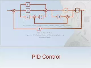
Dynamics and PID control Sigurd Skogestad TexPoint fonts used in EMF. Read the TexPoint manual before you delete this box.: AAAAAAAA
u input y Process Process dynamics • “Things take time” • Step response (response of output y to step in input u): • k = Δy(∞)/ Δu – process gain • - process time constant (63%) • - process time delay • Time constant : Often equal to residence time = V[m3]/q[m3/s] (but not always!) • Dynamic model: Can find (and k) from balance equations: • Rearrange to match standard form of 1st order linear differential equation:
Example dynamic model: Concentration change in mixing tank Inventory outflow inflow • Assume constant V [m3] • Assume constant density ρ [kg/m3] • Assume, c (in tank) = c (outflow) [mol A/m3] • Assume no reaction Balances: Mass Component: c V q [m3/s] qF [m3/s] c cF
Response of linear first-order system Δy(t=∞) = kΔu Remember for first order response: • Starts increasing immediately (would reach new steady state after time ¿ if it kept going) • Reaches 63% of change after time ¿. • Approaches new steady state exponentially (has for practical purposes reached new steady state after about 4¿)
Feedback control Control systems elements: Valve T Card in computer Hot water Measument signal [bits] A/D (convert analog to digital signal) Thermo-couple Signal [mV] Computer (controlleralgorithm) Setpoint, etc. [bar / psi/ Ampere] Motor/ Amplifier/ Relay Signal [mV] D/A (convert digital to analog signal) Input signal [bits] Card in computer
Block diagram Process e ym Block diagram of negative feedback control C = Feedback Controller = ?
Feedback controller Measurement ym Controller Algorithm: u = f(ys-ym) Input (MV) u Setpoint ys Simplest controller algorithm: On/off controller. Problem: cycles Industry: Standard algorithm for SISO controllers: PID Industry: Standard for multivariable control: MPC (model predictive control) y=T u=Q (heat)
PID controller • Proportional control (P) Input change (u-u0) is proportional to control error e. Kc = proportional gain (tuning parameter) u0: = «bias» • Problems proportionalcontrol: • Get steady-state offset (especiallyifKc is small) • OscillatesifKc is toolarge(cangetinstability) k: process gain Kc: controller gain
P-control of typical process y Kc=8/k ys (setpoint) 20% Kc=4/k Kc=2/k 50% offset Kc=1/k Initially at steady-state (y=ys=0). Change setpoint to ys=1 at t=1. Not sure what process it is; a bit similar to theta=0.25,tau=1
Fix: Add Integral action (I) • Get PI-control: ¿I = integral time (tuning parameter) e = ys – y (control error) Note 1: Integral term will keep changing until e=0 ) No steady-state offset Note 2: Small integral time gives more effect! (so set ¿I = 99999 (large!) to turn off integral action) Note 3: Integral action is also called «reset action» since it «resets» the bias. «Update bias u0 at every Δt»:
Add also derivative action (D):Get PID controller D: Impatient P:Normal I: Patient • P-part: MV (Δu) proportional to error • This is usually the main part of the controller! • I-part: Add contribution proportional to integrated error. • Integral keeps changing as long as e≠0 • -> Will eventually make e=0 (no steady-state offset!) • Possible D-part: Add contribution proportional to change in (derivative of) error • Can improve control for high-order (S-shaped response) and unstable processes, but sensitive to measurement noise
Many alternative PID parameterizations • Also other: • Proportional band = 100/Kc • Reset rate = 1/ I • Etc….. • NOTE: Always check the manual for your controller!
Digital implementation (practical in computer) of PID controller Ikke pensum sep.tek
PID controller tuning Want the system to be (TRADE-OFF!) • Fast intitially (Kc large, D large) • Fast approach to steady state (I small) • Robust / stable (OPPOSITE: Kc small, I large) • Smooth use of inputs (OPPOSITE: Kc small, D small)
Tuning of your PID controllerI. “Trial & error” approach (online) • P-part: Increase controller gain (Kc) until the process starts oscillating or the input saturates • Decrease the gain (~ factor 2) • I-part: Reduce the integral time (I) until the process starts oscillating • Increase a bit (~ factor 2) • Possible D-part: Increase D and see if there is any improvement Very common approach, BUT: Time consuming and does not give good tunings: NOT recommended
II. Model-based tuning (SIMC rule) • From step response obtain • k = Δy(∞)/ Δu – process gain • - process time constant (63%) • - process time delay • Proposed SIMC controller tunings k = Δy(∞)/ Δu
Example SIMC rule • From step response • k = Δy(∞)/ Δu = 10C / 1 kW = 10 • = 0.4 min (time constant) • = 0.3 min (delay) • Proposed controller tunings
Simulation PID control • Setpoint change at t=0 and disturbance at t=5 min • Well tuned (SIMC): Kc=0.07, taui=0.4min • Too long integral time (Kc=0.07, taui=1 min) : settles slowly • Too large gain (Kc=0.15, taui=0.4 min) – oscillates • Too small integral time (Kc=0.07, taui=0.2 min) – oscillates • Even more aggressive (Kc=0.12, taui=0.2 min) – unstable (not shown on figure) 3 4 Output (y) 2 1 setpoint 1 2 3 4 Time [min]
Comments tuning • Delay (θ) is feedback control’s worst enemy! • Try to reduce it, if possible. Rule: ”Pair close”! • Common mistake: Wrong sign of controller! • Controller gain (Kc) should be such that controller counteracts changes in output • Need negative sign around the loop (”negative feedback”) • Two ways of achieving this: • (Most control courses:) Use a negative sign in the feedback loop. Then controller gain (Kc) should always have same sign as process gain (k) • (Many real control systems:) Always use Kc positive and select between • ”Reverse acting” when process gain (k) is positive • because MV (u) should go down when CV (y) goes up • ”Direct acting” when k is negative • WARNING: Be careful and read manual! Some reverse these definitions (wikipedia used to do it, but I corrected it) • Oct. 2009: http://en.wikipedia.org/wiki/Controller_(control_theory)
3. Integrating («slow») process: If the response is not settling after approximately 10 times the delay (so ¿/µ is large), then you can stop the experiment and approximate the response as an integrating process (with only two parameters, k’ and µ): Δy Δt
Example: Similar to shower process u = Q y = T d = TF Looong pipe µ=100s ¿=20s Simulink model: tunepid1_ex1 Note: level control not explicitly included in simulation (assume constant level)
Disturbance response with no control d = TF Looong pipe µ=100s u = Q ¿=20s y = T u = Q y = T d = TF Kc=0; taui=9999; % no control %start simulation (press green button) plot(time,u,time,T,time,Tf), axis([0 800 -1.5 1.5])
P-control u = Q y = T d = TF Offset TC Kc=0.5; taui=9999; % P-control %start simulation (press green button) plot(time,u,time,T,time,Tf), axis([0 800 -1.5 1.5]) Ts
SIMC PI control u = Q y = T d = TF No offset TC Kc=0.1; taui=20; % SIMC PI-control %start simulation (press green button) plot(time,u,time,T,time,Tf), axis([0 800 -1.5 1.5]) Ts
d = TF y = T u = Q Recommend: ¿c=delay µ=100s because it is more robust and gives no overshoot in u
Measure also T0: Cascade control is much better d = TF u = Q T0 TC Slave controller (inner loop) y = T T0s TC Ts Master controller (outer loop) Inner loop (T0): tauc=10 Outer loop (T): tauc=105 Kc2=0.1;taui2=1; % inner loop with tauc2=10 Kc=0.119; taui=25; % outer loop with tauc=105 sim('tunepid1_ex1_cascade') %start simulation plot(time,u,time,T,time,Tf,time,T0), axis([0 800 -1.5 1.5])
K5, 11 Nov. 2016 The experimental setup This is the «Whistler» y=T [C] (at top) u=Q [0-1] (at bottom) First we did a step response experiment where u was increased from 0 to 1 (manual vontrol). The temperature y=T increased from 20C to 54C (new steady state). This gives k=68. The dynamics are quite slow because it takes time to heat up the glass. , θ=5s, τ =120s From this we obtained the model parameters and SIMC tunings (with τc=θ=5s) We then put it into automatic andf increased the setpoint to 70C. The input (u=Q) increased immediately to max=1, and we should then have stopped the integration («anit windup») but we had forgotten to do this and this is why you can see that u=Q stayed at max=1 even after y=T has oassed the setpoint…. Not so good… but eventually we see that itr was working well. This can be confirmed by Ida who was the ONLY student who stayed behind to check how things went. Thanks, Ida! y=T Thanks to Tamal Das u=Q Thanks to Ida
The model. Step response: k=68, θ=5s, τ =120sThe controller. SIMC (with τc=θ=5s): Kc=0.2, τI=40s
The closed-loop responseJa, reguleringen virket etter hvert! - noe Ida kan bekrefte y=T ys=Ts =70C max=1 u=Q (The input is a bit noisy because of a noisy temperature measurement, but it works!) min=0 Time (s)