Download
1 / 27
350 likes | 719 Views
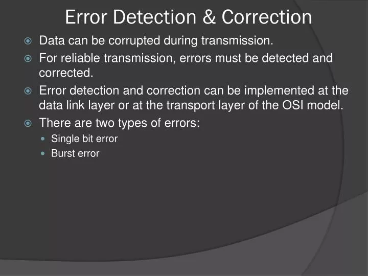
Error Detection & Correction. Data can be corrupted during transmission. For reliable transmission, errors must be detected and corrected. Error detection and correction can be implemented at the data link layer or at the transport layer of the OSI model. There are two types of errors:

E N D
Error Detection & Correction • Data can be corrupted during transmission. • For reliable transmission, errors must be detected and corrected. • Error detection and correction can be implemented at the data link layer or at the transport layer of the OSI model. • There are two types of errors: • Single bit error • Burst error
Single bit error • The single bit error means only one bit get changed of the data unit from 0 to 1 or 1 to 0. • A single bit error can happen if we are sending a data using parallel transmission. • For example, if eight wires are used to send all of the eight bits of a byte at the same time and one of the wire is noisy, one bit can be corrupted in each byte. • In serial transmission, the chances for a single bit error to occur are very less.
Burst error • A burst error means that two or more bits in the data unit have changed. • Burst error most likely to happen in a serial transmission. • The duration of noise is normally longer than the duration of a bit, which means that when noise affects data, it affects a set of bits. • The number of bits affected depends on the data rate and duration of noise.
Error Detection • Method 1: • The sender will send two set of data unit. • The receiving device would then be able to do a bit-for-bit comparison between the two versions of the data. • Any discepancy would indicate an error, and an appropriate correction mechanism could be set in place. • This method would be completely accurate, but it is very slow. • The transmission time will be double and more extra time is added for comparison of every bits.
Error Detection • Method 2 • Instead of repeating the entire data stream, a shorter group of bits may be appended to the end of each data unit. • This technique is called redundancy because the extra bits are redundant to the information. • They are discarded as soon as the accuracy of the transmission has been determined. • Once the data stream has generated, it passes through device that analyzes it and adds on an appropriate coded redundancy check. • The data unit is now enlarged by several bits, travels over the link to the receiver. • The receiver passes the checking criteria, the data portion of the data unit is accepted and the redundant bits are discarded.
Vertical Redundancy Check(VRC) • It is least expensive method of error detection and often called, parity check. • In this technique, a redundant bit, called a parity bit, is appended to every data unit so that the total number of 1s in the unit becomes even. • For example, 1100001 1100001 1 1101010 1101010 0
VRC • Performance • VRC can detect all single bit error. • It can also detect burst errors as long as the total number of bits changed is odd. • For example, 1000111011 • If any three bits get changed then the resulting parity will be odd and error will be detected. • If two bits get changed then, the resulting parity will be even and error will not be detected.
Longitudinal redundancy check (LRC) • In LRC, a block of bits is divided into rows and a redundant row of bits is added to the whole block. • Instead of sending 32 bits , it organize them in a table made of four rows and eight columns. • Then calculate the parity bit for each column and create a new row of eight bits, which are the parity bits for the whole block.
LRC 10101010 LRC Original Data plus LRC
LRC • Performance • LRC increases the likelihood of detecting burst errors. • If two bit pattern of errors are damaged and two bits exactly in the same positions in another data unit are also damaged, the LRC checker will not detect error. • For example, • 11110000 and 11000011 • If the first and last bit in each of them are changed, making the data units read 01110001 and 01000010, the errors can not be detected by LRC.
Hamming Code • Hamming code can be applied to data units of any length and uses relationships between data and redundancy bits . • Redundancy Bits: • R1: bits 1,3,5,7,9,11 • R2 : bits 2,3,6,7,10,11 • R3: bits 4,5,6,7 • R8: bits: 8,9,10,11
Figure 9-21 Single-bit error The McGraw-Hill Companies, Inc., 1998 WCB/McGraw-Hill
Ethernet • Ethernet is IEEE 802.3 standards.
CSMA/CD • A LAN needs a mechanism to coordinate traffic, minimize the number of frames that are delivered successfully. • The access mechanism used in an Ethernet is called carrier sense multiple access with collision detection (CSMA/CD).