Download

1 / 15
260 likes | 704 Views
Xilinx ISE. Tyrell Fawcett, Research Assistant Ryan Hoover, Research Assistant CVORG Labs Electrical and Computer Engineering University of Delaware http://cvorg.ece.udel.edu. ISE Info. ISE Webpack is FREE!! http://www.xilinx.com/tools/webpack.htm. Spartan-3 Family.

E N D
Xilinx ISE Tyrell Fawcett, Research Assistant Ryan Hoover, Research Assistant CVORG Labs Electrical and Computer Engineering University of Delaware http://cvorg.ece.udel.edu
ISE Info • ISE Webpack is FREE!! • http://www.xilinx.com/tools/webpack.htm
Spartan-3 Family Based upon Virtex-II Architecture – Optimized for Lower Cost • Xilinx XC3S500E Spartan-3E FPGA • Up to 232 user-I/O pins • 4Mbit Platform Flash configuration PROM • 64 Mbytes of DDR SDRAM • 16 Mbytes of parallel NOR Flash • 16 Mbits of SPI serial Flash • 2-line, 16-character LCD screen • PS/2 mouse or keyboard port • VGA display port • 10/100 Ethernet • Two 9-pin RS-232 ports • On-board USB-based FPGA/CPLD download/debug interface • 50MHz clock • Eight discrete LEDs • Four slide switches • Four push-button switches
Hardware Pictures RS-232 VGA DDR RAM FX2 Ethernet NOR Flash FPGA Switches / LEDS LCD
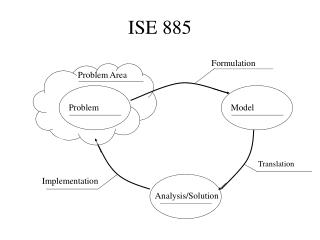
Xilinx Design Flow Plan & Budget Create Code/ Schematic Implement Functional Simulation Synthesize to create netlist Translate Map Place & Route GenerateBIT File Timing Simulation ConfigureFPGA
ISE Project Navigator Xilinx ISE Foundation is built around the Xilinx Design Flow • Enter Designs • Access to synthesis tools • Including third-party synthesis tools • Download • Generate a bitstream • Configure FPGA using iMPACT
Entering Designs • Select source type • Design Entry • Schematic • HDL source (VHDL and Verilog) • Simulation Test Bench • VHDL, Verilog and waveform
Synthesis Generate a netlist file • After coding up your HDL code, you will need a tool to generate a netlist (NGC or EDIF) • Xilinx Synthesis Tool (XST) included • Support for Popular Third Party Synthesis tools: Synplify, Leonardo Spectrum
Netlist File • NET "SW<0>" LOC = "L13" | IOSTANDARD = LVTTL | PULLUP; • NET "SW<1>" LOC = "L14" | IOSTANDARD = LVTTL | PULLUP; • NET "SW<2>" LOC = "H18" | IOSTANDARD = LVTTL | PULLUP; • NET "SW<3>" LOC = "N17" | IOSTANDARD = LVTTL | PULLUP; • NET "LED<7>" LOC = "F9" | IOSTANDARD = LVTTL | SLEW = SLOW | DRIVE = 8 ; • NET "LED<6>" LOC = "E9" | IOSTANDARD = LVTTL | SLEW = SLOW | DRIVE = 8 ; • NET "LED<5>" LOC = "D11" | IOSTANDARD = LVTTL | SLEW = SLOW | DRIVE = 8 ; • NET "LED<4>" LOC = "C11" | IOSTANDARD = LVTTL | SLEW = SLOW | DRIVE = 8 ; • NET "LED<3>" LOC = "F11" | IOSTANDARD = LVTTL | SLEW = SLOW | DRIVE = 8 ; • NET "LED<2>" LOC = "E11" | IOSTANDARD = LVTTL | SLEW = SLOW | DRIVE = 8 ; • NET "LED<1>" LOC = "E12" | IOSTANDARD = LVTTL | SLEW = SLOW | DRIVE = 8 ; • NET "LED<0>" LOC = "F12" | IOSTANDARD = LVTTL | SLEW = SLOW | DRIVE = 8 ;
Implementation Process a netlist file Netlist GeneratedFrom Synthesis • Consists of three phases • Translate: Merge multiple design files into a single netlist • Map: Group logical symbols from the netlist (gates) into physical components (slices and IOBs) • Place & Route: Place components onto the chip, connect the components, and extract timing data into reports . . . Implement . . . Translate Map Place & Route . . .
Configuration • Once a design is implemented, you must create a file that the FPGA can understand • This file is called a bitstream: a BIT file (.bit extension) • The BIT file can be downloaded • Directly into the FPGA • Use a download cable such as Platform USB • To external memory device such as a Xilinx Platform Flash PROM • Must first be converted into a PROM file
Simulating Designs Verify the design with the ISE Simulator 1 Select simulation type • Add a test bench • VHDL, Verilog, or Xilinx waveform file • Perform a Behavioral Simulation • Verfiy that logic is correct • Perform a timing simulation • Verify all of the timing is right 2 Highlight test bench 3 Double-click tosimulate
The Design Summary Displays Design Data • Quick View of Reports, Constraints • Project Status • Device Utilization • Design Summary Options • Performance and Constraints • Reports
Device Utilization Summary Get quick access to used and available resources through the FPGA Design Summary Design Utilization Summary
Demo Time Let’s go to a DEMO!