Download
1 / 23
240 likes | 456 Views
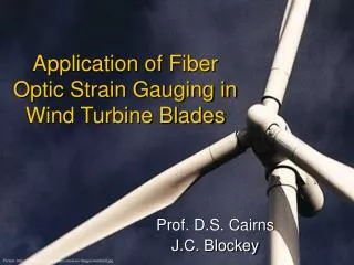
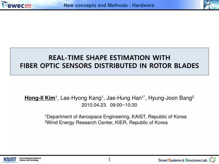
REAL-TIME SHAPE ESTIMATION WITH FIBER OPTIC SENSORS DISTRIBUTED IN ROTOR BLADES. Hong-Il Kim 1 , Lae-Hyong Kang 1 , Jae-Hung Han 1* , Hyung-Joon Bang 2 2010.04.23 . 09:00~10:30 1 Department of Aerospace Engineering, KAIST, Republic of Korea

E N D
REAL-TIME SHAPE ESTIMATION WITH FIBER OPTIC SENSORS DISTRIBUTED IN ROTOR BLADES Hong-Il Kim1,Lae-HyongKang1,Jae-Hung Han1*, Hyung-Joon Bang2 2010.04.23. 09:00~10:30 1Department of Aerospace Engineering, KAIST, Republic of Korea 2Wind Energy Research Center, KIER, Republic of Korea
Experiments Introduction Conclusion Numerical Study Outline
Introduction- Research Backgrounds (Condition monitoring with Shape estimation)- Why Fiber Bragg Grating sensors? - Shape Estimation based on Measured Strains Using FBG Sensors - Research objectives
Condition Monitoring for Reliability Sense What? Full-scale Testing Condition Monitoring Appropriate Environmental Conditions • Strains • Loads • Cracks • Dry-spots • Voids • Operational Dynamics • Temperature gradients • Lightening High-Reliability WT Blade Accurate Loads- Design Requirements O & M Data Base Designed-in Maintainability Designed-in Reliability Reliability Analysis Blade shape(Deformation) Rumsey, 2009, “Condition Monitoring and Wind Turbine Blades,” Wind Turbine Reliability Workshop
Why blade shapes are important? The “Blades” • The shapes of the “Blades” influence the whole systems’ status Design Validation Status Monitoring Active control for blades Blade Shape Information - Bending => Flapping motion - Torsion => Pitching motion
Why blade shapes are important? Direct Shape Measurement Optical image processing techniques Pattern (NASA Langley) Marker(DNW) PMI (Projection MoireInterferometry) SPR(Stereo Pattern Recognition) • It is difficult to directly monitor the shape changes on operation. Shape estimation On operation • The real-time shape estimation techniques based on embeddable sensors
Why Fiber Bragg grating sensor? • Typical embeddable sensors (Strain gauge, accelerometer..) • Complex electric-wiring (Slip ring) + Significant measurement noise • FBG (Fiber Bragg Grating) sensor • Small, lightweight, High sensitivity, Electro-magnetic immunity • No hygro-effects and easily installable onto/into host structures. • Multiplexing • Real time strain acquisition • FBG sensors are already applied to the load monitoring Optical Rotary Joint Slip ring [1] [2] [1] A fibre Bragg grating sensor system monitors operational load in a wind turbine rotor blade [2] Advanced Wing Turbine Controls Input Based on Real Time Loads Measured with Fibre Optical Sensors embedded in Rotor Blades
Discrete strains Shape Estimation based on Measured Strains Using FBG Sensors – previous works • Estimation model using • modal approach • FEM data e State Space Weighting matrix Kk C [DST] Integration of the filtering technologies Real-time shape estimation of the Rotating structures Real time Shape Estimation of a Two-Dimensional Structure Error covariances w C’F Fr full state vectordisplacement field Output matrix State matrix Distributed FBG sensors
Research objectives • Primary objectives • Development and validation of a real-time shape estimation technique for Wind Turbine blades using FBG sensors • Research steps • Numerical study on the shape estimation method for the rotating beams • Rotating beam dynamics are simulated. (displacement fields, a few strain data) • Displacement is reconstructed using strains • Shape estimation method is evaluated through the comparison between original displacements and the estimated displacements. • Sensor location is optimized. • Experimental Demonstration of the real-time shape estimation for the rotating structures • FBG sensors are used to measure multi-point strains of the beam. • Structural deformation shape of the rotating beam is estimated. • The estimated shapes are compared with the directly measured shapes using photogrammety.
Numerical Study- Simulation Steps - Simulation Results - Optimization of Sensor locations
Virtual experiments – simulation steps Rotating beam motions are simulated - Full-field Displacement & strain Shape estimation DST matrix constructed Discrete strains Sensor location Optimization FMD Full-field Strain & Displacement Beam model Sensor location Evaluation Mode shapes M : # of sensors, N : # of disp. Points, n : # of used modes
Simulation Results Directly Simulated Deflection • Rotating beam dynamics are simulated • Full-field displacement & distributed strain Comparison Full-field Displacement Discrete strains • Strains at a few points are used for reconstruction of full-field displacement via DST matrix. Estimated Deflection
Simulation Results Rotating beam displacement at the Tip of the beam (Numerical simulation vs. Shape estimation results) Numerical simulation Shape estimation Directly Simulated Reconstructed fromstrains • Shape estimation using simulated strains are performed • Full-field displacement from numerical simulation are compared with Estimated shape using strains
Optimization of Sensor locations Estimated displacement Measured strain DST matrix (Displacement Strain Transformation) Condition number • Used as the objective function for sensor location optimization • Small condition number indicates good information conservation during matrix operations Initial Seed Sensor 1: 0~4cm Sensor 2: 5~16cm Sensor 3: 19~31cm Sensor 4: 33~38cm Condition Number of DST Sensor position CN=19, (4.0,15.0,21,33)
Experiments –rotating beam- Rotating beam test setup - Test measurand/DST matrix - Results
Test setup – Demonstration of the rotating beam Reconstructed shape (DST) Photo-grammetry fbg1 fbg2 fbg3 Images taken by High-speed camera fbg4 Optical rotary joint
Test measurand • Measurand • Four Strains (FBG sensors) • 13 Marker positions (Photogrammety) • Angular position Strain by FBG 60RPM case Rotating angle
DST matrix • Acrylic beam (500mm×20mm×1.9mm) was used for denstrating large deflection in low speed Optimized sensor locations fbg1 fbg2 fbg3 fbg4 Marker positions FBG position Marker position DST matrix
Results – qualitative aspects 30 RPM rotation 60 RPM rotation
Results -Shape comparison between DST vs. Images Directly Measured (High Speed Camera) Estimated (from strains using FBG)
Results – quantitative aspects Time [s] Pole effect Skewed distribution
Development of the shape estimation technique for a rotating structure • A real-time deflection of the rotating beam is successfully estimated based displacement -strain transformation • - Sensor location optimization is executed. • - From the test results, it is clear that beam shape estimation of the rotating beam is successfully performed based on DST method and strain data obtained by FBG sensors. • FBG(Fiber Bragg grating) sensor is selected as a strain sensor because of many inherent advantages of fiber optic sensors and multiplexing capability. Conclusion
THANK YOU! Hong-Il Kim (hama@kaist.ac.kr) Ph. D. candidate Aerospace Engineering, KAIST Jae-Hung Han (jaehunghan@kaist.ac.kr) Associate Prof. Aerospace Engineering, KAIST Smart Systems and Structures Lab. : Design & Control Visit our website: http://sss.kaist.ac.kr • Acknowledgments • This work was supported by the Korea Institute of Energy Research through the research project (grant No. NT2009-0008).