Download
1 / 15
190 likes | 430 Views
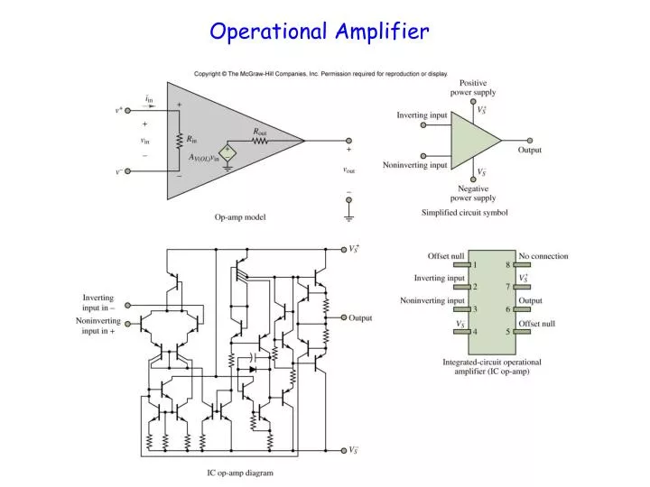
Operational Amplifier. Ideal OP Amp. Circuit model. i in =0, no current flow into op amp. V + =V - Typically one end of op amp is connected to ground, therefore, V + =V - = 0V, virtual ground. Often V + is connected to ground to avoid stability problem.

E N D
Ideal OP Amp Circuit model • iin=0, no current flow into op amp. • V+=V- • Typically one end of op amp is connected to ground, therefore, V+=V-= 0V, virtual ground. Often V+ is connected to ground to avoid stability problem. Two golden rules to perform calculations on op amps with negative feedback:
Applications: building block for analog systems • Amplifiers • Adders and Substractors • Integrators & Differentiators • Clock generators • Filters • Digital-to-analog converters
Using op-amps No flexibility
When A is very large Suppose A=106, R1=9R, R2=R • Gain: • determined by resistance ratio • insensitive to A, temperature, fab variation
Why did this happen? Negative feedback e.g. vIN=5V Suppose I perturb the circuit (e.g. force v0 momentarily to 12V somehow Stable point is when v+v- Key: negative feedback portion of output fed to –ve input. e.g. Car antilock brakes small corrections
How to control a high-strung device • Antilock brakes
More op amp insights: • Observe, under negative feedback, • We also know • i+ 0 • i- 0 Yield an easier analysis method (under negative feedback)
Voltage follower Why is this circuit useful? has minimum effects on previous and next circuit.
Inverting Amplifier Feedback resistor, always to negative input
Summing Amplifier: Add Circuit If RS1=RS2=…=RSN=RS
Non-innverting Amplifier Feedback resistor, always to negative input
Differential Amplifier: Substractor Very useful if both signals are corrupted with noise: Electrocardiogram (EKG)